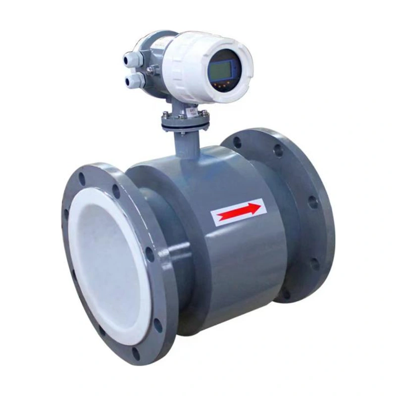
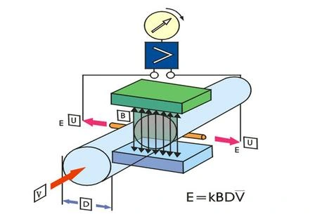
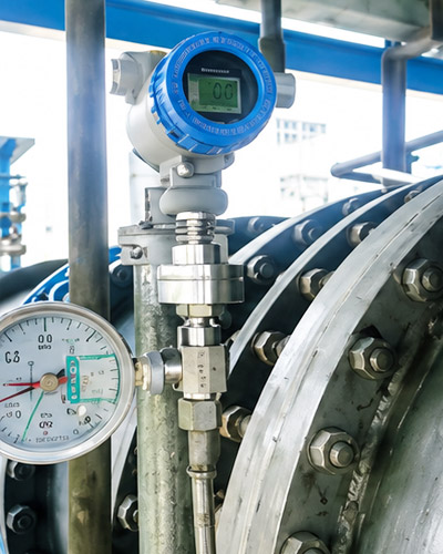
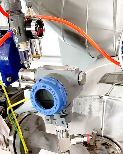
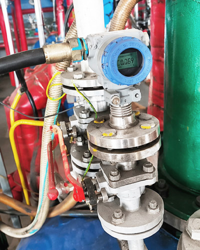
The ADDA-FL-DC measures the volumetric flow of conductive liquids using Faraday’s law of electromagnetic induction. The system consists of a flow sensor and a converter, with integral and remote configurations available. Electrodes detect the voltage generated as the liquid passes through the magnetic field.
Features
Unobstructed measuring tube with no moving flow-restricting components.
Accuracy grades of 1.0, 0.5 and 0.2, selected to suit the application.
Electrode, liner and body material options for different conductive liquids.
Pulse, frequency, 4–20 mA, optional HART, and Modbus RTU over RS485 output options.
애플리케이션
Suitable applications include power generation, metallurgy, chemical processing, petroleum and petrochemical processes, municipal water systems, environmental treatment, food processing and pharmaceutical production. Select the wetted materials, lining, connections and temperature rating for the actual medium and operating conditions.
Operating Principle
The induced voltage is proportional to liquid velocity when the magnetic field and pipe diameter are fixed. The catalogue expresses this relationship as E = B × V × D, where E is induced voltage, B is magnetic flux density, V is mean liquid velocity and D is the internal pipe diameter. Volumetric flow is Q = V × πD² / 4.
Electromagnetic measurement principle
Technical Specifications
Parameter
Specification
Applicable medium
Conductive liquids with conductivity ≥5 μS/cm
Product standard listed in the catalogue
JB/T 9248-2015
Body and flange materials
Carbon steel, 304 stainless steel or 316 stainless steel
Threaded connection sizes
DN15–DN50
Flanged connection sizes
DN4–DN300
Clamp connection sizes
DN15–DN100
Medium temperature
−20°C to +150°C; actual limits depend on lining and configuration
Ambient temperature
−20°C to +55°C
Ambient relative humidity
5%–95%
Accuracy grades
1.0, 0.5 or 0.2
Repeatability
Better than one third of the absolute maximum permissible error for the selected accuracy grade
IP65, IP67 or IP68, depending on the selected configuration
Liner Temperature Limits
The liner limit does not override the complete meter’s specified operating limit. Confirm the usable temperature range for the selected assembly.
Liner
Remote configuration
Integral configuration
PTFE or PFA
−30°C to +150°C
−30°C to +80°C
F46
−30°C to +100°C
−30°C to +80°C
Neoprene
−15°C to +80°C
−15°C to +80°C
Polyurethane
−15°C to +60°C
−15°C to +60°C
Pressure Ratings by Connection
Pressure ratings are connection- and size-dependent. A dash indicates that the connection is not listed for that size.
Pressure Ratings by Connection — Threaded PN and Flanged PN
Nominal size
Threaded PN
Flanged PN
DN4
—
10~40
DN6
—
10~40
DN10
—
10~40
DN15
16
10~160
DN20
16
10~160
DN25
16
10~160
DN32
16
10~160
DN40
16
10~160
DN50
16
10~160
DN65
—
10~160
DN80
—
10~160
DN100
—
10~160
DN125
—
10~160
DN150
—
10~160
DN200
—
10~40
DN250
—
10~40
DN300
—
10~40
Pressure Ratings by Connection — Flanged Class and Clamp PN
Nominal size
Flanged Class
Clamp PN
DN4
—
—
DN6
—
—
DN10
—
—
DN15
150~900
10
DN20
150~900
10
DN25
150~900
10
DN32
150~900
10
DN40
150~900
10
DN50
150~900
10
DN65
150~900
10
DN80
150~900
10
DN100
150~900
10
DN125
150~900
—
DN150
150~900
—
DN200
150~300
—
DN250
150~300
—
DN300
150~300
—
Configuration Options
항목
Available options
Construction
Integral or remote
Electrode materials
316L, HC, titanium, tantalum, platinum or tungsten carbide
Lining
Neoprene, polyurethane, PTFE, F46 or PFA
Body materials
Carbon steel, 304 stainless steel or 316 stainless steel
Electrical entries
M20 × 1.5 or 1/2 NPT
Grounding arrangements
No grounding ring, grounding ring or grounding electrode; grounding electrode material matches the measuring electrode material
Hazardous-area option
Flameproof option listed as Exdb IIC T6 Gb; a non-explosion-protected option is also listed. Confirm the applicable marking and documentation for the ordered configuration.
Specify the required flange standard and sealing face, or the thread or clamp dimensions, when ordering.
Flanged Dimensions
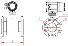
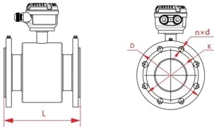
Dimensions below are in millimetres and apply to the PN10 flange arrangement shown.
Integral flanged meter dimensionsRemote sensor dimensions
PN10 flanged dimensions in mm
Nominal size
L
D
K
n × d
4
200
90
60
4×φ14
6
200
90
60
4×φ14
10
200
90
60
4×φ14
15
200
95
65
4×φ14
20
200
105
75
4×φ14
25
200
115
85
4×φ14
32
200
140
100
4×φ18
40
200
150
110
4×φ18
50
200
165
125
4×φ18
65
200
185
145
8×φ18
80
200
200
160
8×φ18
100
250
220
180
8×φ18
125
250
250
210
8×φ18
150
300
285
240
8×φ22
200
350
340
295
8×φ22
250
450
395
350
12×φ22
300
500
445
400
12×φ22
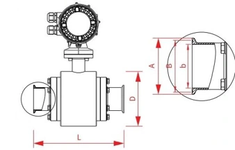
Clamp Dimensions
Clamp connection dimensions
Clamp dimensions in mm — Part 1 of 2
Nominal size
L
D
A
15
200
108
34
20
200
108
34
25
200
108
50.5
32
200
108
50.5
40
250
126
64
50
250
151
64
65
250
151
77.5
80
250
201
91
100
250
201
119
Clamp dimensions in mm — Part 2 of 2
Nominal size
B
b
15
27.5
12.7
20
27.5
17.2
25
43.5
22.6
32
43.5
31.3
40
56.5
37.6
50
56.5
48.6
65
70.5
60.3
80
83.5
72.9
100
110
97.6
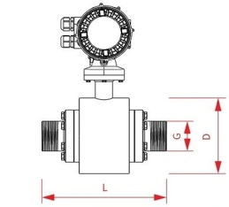
Threaded Dimensions
Threaded connection dimensions
Threaded dimensions in mm
Nominal size
L
D
Thread G
15
200
108
G1/2
20
200
108
G3/4
25
200
108
G1
32
200
108
G1 1/4
40
250
126
G1 1/2
50
250
151
G2
Installation Guidance
Upstream disturbance
Upstream straight length
Downstream straight length
Two-dimensional bend
5 × DN
2 × DN
Three-dimensional bend
10 × DN
2 × DN
Tee
10 × DN
2 × DN
Keep the measuring tube full. Prefer a low point or rising pipe section; avoid high points where air can accumulate.
Avoid a vertical arrangement discharging directly to an open outlet unless back pressure is controlled.
Prefer installation downstream of a pump after flow disturbances have subsided, and upstream of a control valve. Avoid cavitation.
If the drop to the discharge valve exceeds 5 m, provide a vent at the highest point above the flow meter as shown in the installation design.
Align the converter above or below the pipe axis. Keep mating flanges parallel; the catalogue specifies Lmax − Lmin < 0.5 mm for flange-face misalignment.
Ground the meter according to the applicable installation requirements.