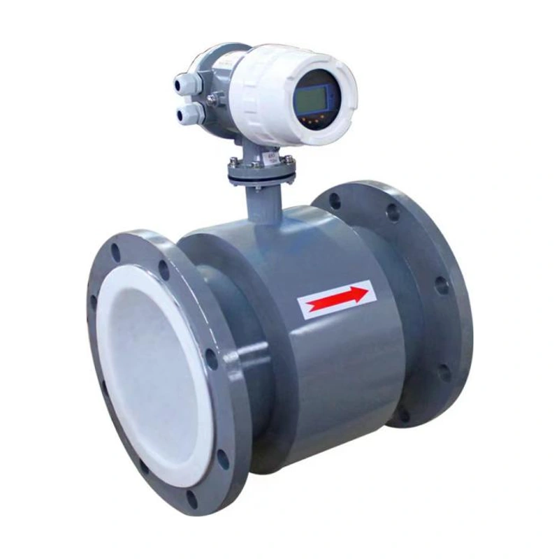
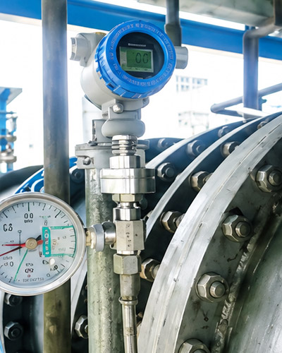
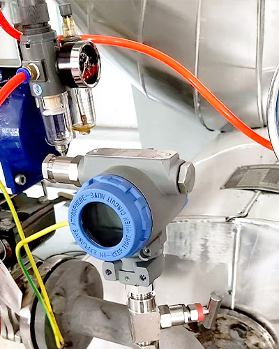
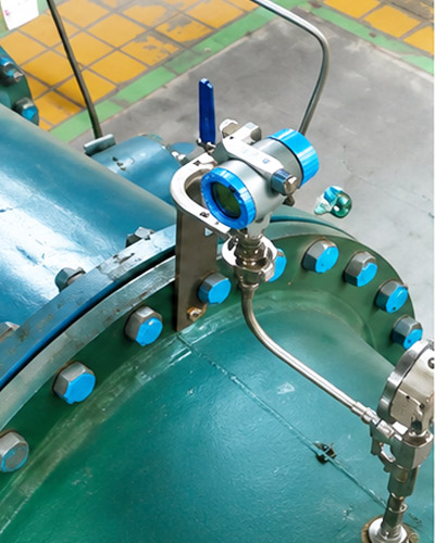
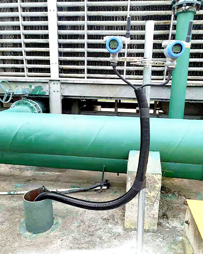
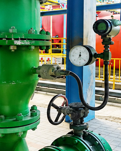
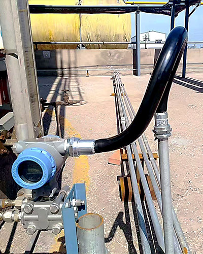
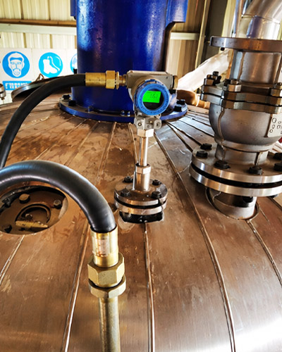
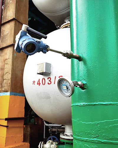
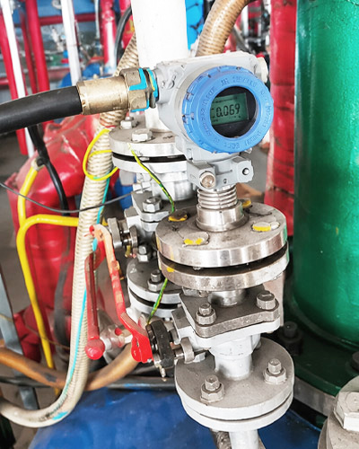
مقياس تدفق التوربينات السائلة للسوائل النظيفة ومنخفضة اللزوجة. تتوفر خيارات DN4 hoardN300 مع وصلات ملولبة أو ذات حواف أو رقاقة أو مشبك صحي. حدد إلكترونيات GA بدون شاشة عرض محلية أو إلكترونيات GN مع شاشة LCD متكاملة، مع خيارات الإخراج لتناسب نظام التحكم.
شهادات التأهيل الرسمية
نحن حاصلون على شهادة الجودة ISO، ومؤهلات المؤسسات الوطنية عالية التقنية، والموافقة على نوع أداة القياس الصينية، وشهادات مقاومة الانفجار والسلامة لدعم جودة المنتج الموثوقة.
الهندسة المخصصة
مواد قابلة للتكوين، واتصالات، وإشارات، وشاشات عرض، وحلول تثبيت لبيئات العمليات المختلفة.
The ADDA-FL-WL is a velocity-type turbine flow meter for clean, low-viscosity liquids that are not strongly corrosive. Liquid passing through the meter drives a rotor; its speed is converted into an electrical signal proportional to flow. The series is used in food and pharmaceutical processing, fine chemicals, petroleum and other liquid measurement applications.
Select the wetted materials, process connection and electronics to suit the liquid, operating pressure, temperature and required flow range.
سمات
Nominal sizes from DN4 to DN300, depending on connection type.
GA versions without local display and GN versions with an integral LCD.
Pulse, 4–20 mA, Modbus RTU over RS485 and HART options, depending on electronics.
GN versions display volumetric flow and can calculate mass flow from a configured liquid density.
Threaded, flanged, wafer and sanitary clamp connection options.
مبدأ التشغيل
The flowing liquid applies torque to the angled turbine blades. Within the calibrated operating range, rotor speed is proportional to average liquid velocity. A magnetic pickup detects the rotating blades and generates pulses; the electronics process these pulses to indicate instantaneous flow and totalized volume.
Q = 3.6 × f / K, where Q is volumetric flow at operating conditions in m³/h, f is pulse frequency in Hz, and K is the meter factor in pulses per litre. Use the meter factor stated in the individual calibration report.
Turbine flow measurement principle
المواصفات الفنية
معلمة
تخصيص
Model
ADDA-FL-WL
Suitable liquids
Clean liquids without solid impurities; kinematic viscosity below 10 mm²/s; not strongly corrosive
Meter body
304 or 316 stainless steel
Rotor materials, DN4–DN125
2Cr13 stainless steel or 2205 duplex stainless steel
Rotor materials, DN150–DN300
304 hub with 430 blades, or 316 hub with 2205 duplex stainless steel blades
Process temperature
−40 to +120°C or −40 to +150°C, depending on version; −40 to +80°C option also listed in the ordering guide
Ambient temperature
−20 to +60°C
Relative humidity
5–95%
تصنيف الضغط
PN10–PN400 or Class 150–2500, depending on nominal size and connection
Accuracy options
Version-dependent; see electronics table below. Class 0.2 is available on request.
Referenced product standard
JB/T 9246-2016, Turbine Flow Sensors
Referenced verification regulation
JJG 1037-2008, Turbine Flowmeters
خيارات اتصال العملية
Connection
Available nominal sizes
External thread
DN4–DN80
Internal thread
DN4–DN50
Flanged
DN4–DN300
Wafer
DN15 رزينDN200
Sanitary clamp
DN4–DN100
Electronics Versions
معلمة
GA without local display
GN with integral LCD
Function
Remote transmission for flow computers, PLCs and control systems
Local indication and remote signal transmission
Accuracy classes
2.5, 1.5, 1.0 or 0.5
0.5, 0.3 or 0.2; class 0.2 on request
Repeatability
Better than 0.15%
Better than 0.15%
مصدر طاقة
24 V DC nominal; 5–32 V DC or 16–32 V DC depending on output
24 V DC
خيارات الإخراج
Pulse or 4–20 mA
Pulse or two-wire 4–20 mA; HART and Modbus RTU over RS485 configurations available
Electrical connections
Circular plug, cable lead or Hirschmann-type connector
M20 × 1.5 or 1/2 NPT
حماية الدخول
IP65 or IP67, depending on version
IP67
Output, power-supply and protection options must be selected as a compatible configuration. Hazardous-area versions are available on request; confirm the marking and applicable certification for the supplied unit.
Liquid Flow Ranges
الحجم الاسمي
Flow range (m³/h)
DN4
0.04–0.4
DN6
0.06–0.6
DN10
0.15–1.5
DN15
0.5–6
DN20
0.45–9
DN25
0.5–10
DN32
0.8–15
DN40
1–20
DN50
2–40
DN65
5–70
DN80
7–100
DN100
10–200
DN125
13–250
DN150
15–300
DN200
40–800
DN250
100–1000
DN300
120–1200
Select a size so that the normal operating flow is preferably within 20–80% of the selected meter’s maximum flow. Confirm suitability against liquid properties and process conditions.
Pressure Rating Options
Pressure Rating Options — Part 1 of 3
Size
External thread PN
Internal thread PN
Flanged PN
DN4
16–63
16–63
16–63
DN6
16–63
16–63
16–63
DN10
16–63
16–63
16–63
DN15
16–63
16–63
16–250
DN20
16–63
16–63
16–250
DN25
16–63
16–63
16–250
DN32
16–63
16–63
16–250
DN40
16–63
16–63
16–250
DN50
16–63
16–63
16–250
DN65
16–63
—
16–250
DN80
16–63
—
16–250
DN100
—
—
16–250
DN125
—
—
16–250
DN150
—
—
16–250
DN200
—
—
16–250
DN250
—
—
16–40
DN300
—
—
16–40
Pressure Rating Options — Part 2 of 3
Size
Flanged Class
Wafer PN
Wafer Class
DN4
—
—
—
DN6
—
—
—
DN10
—
—
—
DN15
150–1500
63–400
150–2500
DN20
150–1500
63–400
150–2500
DN25
150–1500
63–400
150–2500
DN32
150–1500
63–400
150–2500
DN40
150–1500
63–400
150–2500
DN50
150–1500
63–400
150–2500
DN65
150–1500
63–400
150–2500
DN80
150–600
63–400
150–2500
DN100
150–600
63–400
150–2500
DN125
150–600
63–400
150–2500
DN150
150–600
63–400
150–2500
DN200
150–300
63–400
150–2500
DN250
150–300
—
—
DN300
150
—
—
Pressure Rating Options — Part 3 of 3
Size
Clamp PN
DN4
10
DN6
10
DN10
10
DN15
10
DN20
10
DN25
10
DN32
10
DN40
10
DN50
10
DN65
10
DN80
10
DN100
10
DN125
—
DN150
—
DN200
—
DN250
—
DN300
—
PN and Class are separate rating systems. Available ratings depend on the connection and size. Entries marked “—” are not specified here; confirm on request.
Selection Options
اختيار
شفرة
خيار
Electronics
GA
Without local display
Electronics
جي إن
Integral LCD
Connection
F1
Flanged
Connection
F2
Wafer
Connection
F3
Sanitary clamp
Connection
L1
External thread
Connection
L2
Internal thread
Body material
4
304 ستانلس ستيل
Body material
6
316 stainless steel
Rotor material
2C
2Cr13 stainless steel
Rotor material
25
2205 duplex stainless steel
إخراج
GA1
24 V DC, no local display, 4–20 mA
إخراج
GA2
24 V DC, no local display, pulse
إخراج
GN1
24 V DC, local display, pulse
إخراج
GN2
24 V DC, local display, 4–20 mA
إخراج
GN3
24 V DC, local display, 4–20 mA + HART
إخراج
GN4
24 V DC, local display, Modbus RTU over RS485
Temperature
1
−40 to +80°C
Temperature
2
−40 to +120°C
Temperature
3
−40 to +150°C
Hazardous-area requirement
N
Non-explosion-protected version
Hazardous-area requirement
D
Flameproof version; confirm marking and certification for the selected configuration
State the required nominal size, pressure rating, accuracy class, electrical connection and transmitter appearance when ordering. The final configuration must be confirmed for the application.
أبعاد
Dimensions are in millimetres unless otherwise stated. Use the dimensional drawing and table for the selected connection and pressure rating.
External Thread Connection
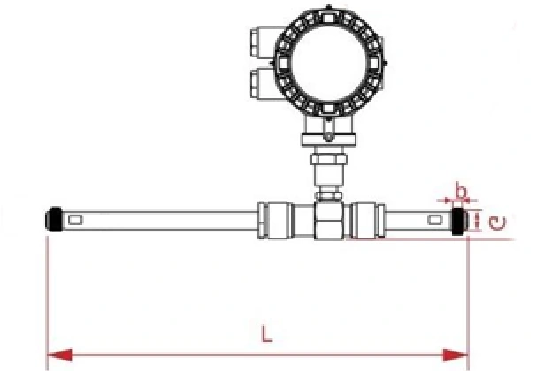
External-thread connection, DN4–DN10, with straight pipe sectionsExternal-thread connection, DN15–DN80
DN4–DN10 external-thread versions include straight pipe sections. DN15–DN80 versions do not include straight pipe sections.
Size
تصنيف الضغط
لام (مم)
G male thread
b (mm)
DN4
PN63 or lower
296
G1/2
13
DN6
PN63 or lower
296
G1/2
13
DN10
PN63 or lower
413
G1/2
13
DN15
PN63 or lower
75
G1
15
DN20
PN63 or lower
85
G1
15
DN25
PN63 or lower
100
G1-1/4
15
DN32
PN63 or lower
140
G2
20
DN40
PN63 or lower
140
G2
20
DN50
PN63 or lower
150
G2-1/2
30
DN65
PN63 or lower
170
G3
35
DN80
PN63 or lower
200
G4
40
Internal Thread Connection
Internal-thread connection, DN4–DN50
Size
تصنيف الضغط
لام (مم)
G female thread
د (مم)
DN4
PN63 or lower
75
G3/8
42
DN6
PN63 or lower
75
G3/8
42
DN10
PN63 or lower
75
G1/2
42
DN15
PN63 or lower
100
G1/2
44
DN20
PN63 or lower
120
G3/4
43
DN25
PN63 or lower
120
G1
49
DN32
PN63 or lower
120
G1-1/4
56
DN40
PN63 or lower
120
G1-1/2
60
DN50
PN63 or lower
120
G2
72
Flanged Connection
Small-bore flanged connection with straight pipe sectionsFlanged connection dimensions
PN flange dimensions — Part 1 of 2
Size
تصنيف الضغط
لام (مم)
د (مم)
DN4
PN40 or lower
296
95
DN6
PN40 or lower
296
95
DN10
PN40 or lower
413
95
DN15
PN40 or lower
75
95
DN20
PN40 or lower
85
105
DN25
PN40 or lower
100
115
DN32
PN40 or lower
140
140
DN40
PN40 or lower
140
150
DN50
PN40 or lower
150
165
DN65
PN16
170
185
DN80
PN16
200
200
DN100
PN16
220
220
DN125
PN16
250
250
DN150
PN16
300
285
DN200
PN16
350
340
DN250
PN16
400
405
DN300
PN16
350
460
PN flange dimensions — Part 2 of 2
Size
K (mm)
d (mm)
n holes
DN4
65
14
4
DN6
65
14
4
DN10
65
14
4
DN15
65
14
4
DN20
75
14
4
DN25
85
14
4
DN32
100
18
4
DN40
110
18
4
DN50
125
18
4
DN65
145
18
8
DN80
160
18
8
DN100
180
18
8
DN125
210
18
8
DN150
240
22
8
DN200
295
22
12
DN250
355
26
12
DN300
410
26
12
Class 150 flange dimensions — Part 1 of 2
Size
Pressure class
لام (مم)
د (مم)
DN4
Class150
296
90
DN6
Class150
296
90
DN10
Class150
413
90
DN15
Class150
75
90
DN20
Class150
85
100
DN25
Class150
100
110
DN32
Class150
140
115
DN40
Class150
140
125
DN50
Class150
150
150
DN65
Class150
170
180
DN80
Class150
200
190
DN100
Class150
220
230
DN125
Class150
250
255
DN150
Class150
300
280
DN200
Class150
350
345
DN250
Class150
400
405
DN300
Class150
350
485
Class 150 flange dimensions — Part 2 of 2
Size
K (mm)
d (mm)
n holes
DN4
60.3
16
4
DN6
60.3
16
4
DN10
60.3
16
4
DN15
60.3
16
4
DN20
69.9
16
4
DN25
79.4
16
4
DN32
88.9
16
4
DN40
98.4
16
4
DN50
120.7
18
4
DN65
139.7
18
4
DN80
152.4
18
4
DN100
190.5
18
8
DN125
215.9
22
8
DN150
241.3
22
8
DN200
298.5
22
8
DN250
362
26
12
DN300
431.8
26
12
Wafer Connection
Wafer connection dimensions
Size
تصنيف الضغط
لام (مم)
د (مم)
DN15
PN400 or lower
65
53
DN20
PN400 or lower
60
53
DN25
PN400 or lower
60
58
DN32
PN400 or lower
70
66
DN40
PN400 or lower
70
72
DN50
PN400 or lower
70
92
DN65
PN400 or lower
80
100
DN80
PN400 or lower
90
112
DN100
PN400 or lower
100
137
DN125
PN400 or lower
120
165
DN150
PN400 or lower
150
190
DN200
PN400 or lower
150
242
The catalogue gives the same wafer body dimensions across the available pressure ratings. When supplied with mating weld-neck flanges, total length equals the standard body length plus twice the mating-flange thickness.
Sanitary Clamp Connection
Sanitary clamp connection dimensionsSanitary clamp connection end view
Sanitary Clamp Connection — Part 1 of 2
Size
تصنيف الضغط
لام (مم)
د (مم)
DN4
PN10
50
50.5
DN6
PN10
50
50.5
DN10
PN10
50
50.5
DN15
PN10
100
50.5
DN20
PN10
100
50.5
DN25
PN10
100
50.5
DN32
PN10
120
50.5
DN40
PN10
140
64
DN50
PN10
150
77.5
DN65
PN10
170
91
DN80
PN10
200
106
DN100
PN10
220
130
Sanitary Clamp Connection — Part 2 of 2
Size
d (mm)
ج (مم)
DN4
4
43.5
DN6
6
43.5
DN10
10
43.5
DN15
15
43.5
DN20
20
43.5
DN25
25
43.5
DN32
32
43.5
DN40
40
56.5
DN50
50
70.5
DN65
65
83.5
DN80
80
97
DN100
100
122
Installation Requirements
Requirement
Guidance
Straight pipe after reducers, expanders or elbows
Provide at least 15D upstream and 5D downstream. D is the nominal internal diameter of the flow meter.
Pipe alignment
Align the meter and pipeline concentrically before installation.
Cleanliness
Flush new pipework before fitting the meter to remove welding debris and other foreign material.
Process connections
Use the mating fittings, gaskets, fasteners and sealing method appropriate to the selected thread, flange, wafer or clamp connection.
يرجى تقديم الوسيط المقاس ونطاق القياس ودرجة حرارة العملية وضغط العملية ونوع الاتصال وإشارة الخرج وإمدادات الطاقة وبيئة التثبيت وطريقة الاتصال إذا كانت المراقبة عن بعد مطلوبة.
نعم. يمكن لفريقنا المساعدة في التوصية بتكوين مناسب للأداة بعد مراجعة شروط التطبيق الخاصة بك، بما في ذلك متطلبات المتوسط والمدى والاتصال وإشارة الخرج والتركيب.
تعتمد المهلة الزمنية على نوع المنتج والكمية ومتطلبات التخصيص واحتياجات إصدار الشهادات. عادةً ما يكون للمنتجات القياسية وقت تسليم أقصر، بينما قد تتطلب النماذج المخصصة وقتًا إضافيًا للإنتاج.