نظرة عامة على المنتج
The ADDA-FL-TY Oval Gear Flow Meter is a positive displacement meter for measuring liquids in a completely filled pipe. A pair of intermeshing oval gears divides the liquid into fixed volumes. The number of gear rotations is used to determine the volume passing through the meter.
It is suitable for oil and fuel metering, as well as clean liquids such as lubricating oil, resins, adhesives and syrups. The meter configuration, wetted materials and seals must be selected for the liquid, viscosity, pressure and temperature of the application.
الميزات الرئيسية
- Positive displacement measurement for a wide range of liquid viscosities.
- 0.5% accuracy, with a 0.2% option.
- No upstream or downstream straight pipe run required.
- LCD indication with pulse, 4–20 mA and RS485 output options.
- Standard, high-temperature, high-viscosity and jacketed configurations available.
- Simple, established mechanical construction with good repeatability.
- Typical turndown ratio of 10:1; the applicable range depends on viscosity and configuration.
- Relatively low pressure loss; actual pressure drop depends on the fluid and operating flow.
مبدأ التشغيل
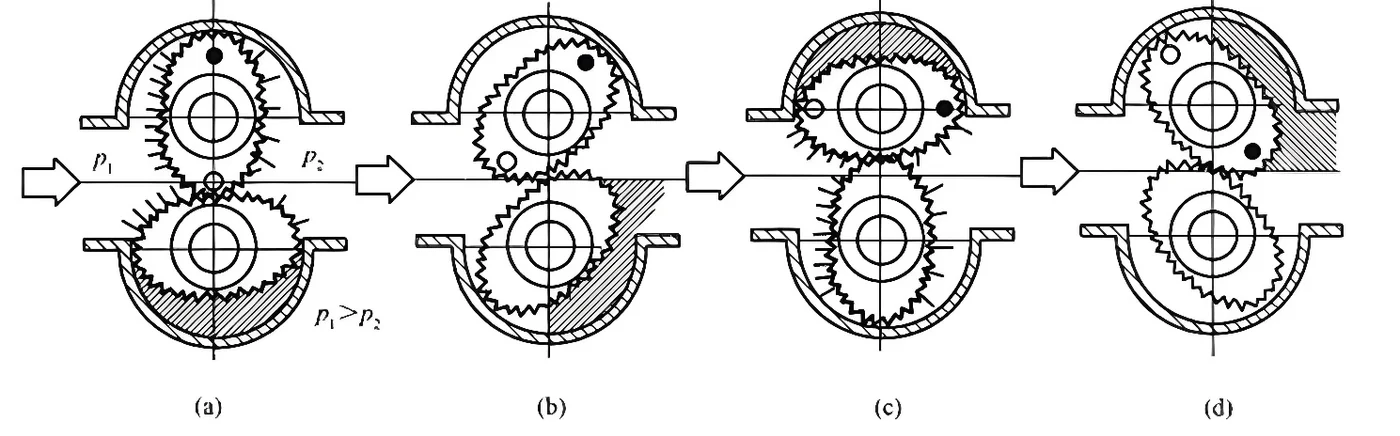
The pressure difference between the inlet and outlet (ΔP = P₁ − P₂) drives a pair of intermeshing oval gears in the measuring chamber. The gears, housing and cover form crescent-shaped measuring cavities. As the gears rotate, they carry fixed volumes of liquid from the inlet to the outlet.
The two gears alternately act as the driving and driven gear. Each quarter-turn displaces one cavity volume; one full revolution displaces four cavity volumes. Gear rotation is transmitted to the counting mechanism through a magnetic coupling or sealed coupling.
Totalized volume: V = 4 × u₀ × n, where u₀ is the volume of one crescent-shaped cavity and n is the total number of gear revolutions.

Four stages of oval gear rotation. Click the diagram to view the full-size image.
المواصفات الفنية
| معلمة | تخصيص |
|---|
| Model | ADDA-FL-TY |
|---|
| Measuring principle | Positive displacement with oval gears |
|---|
| Nominal diameter | DN10–DN200 |
|---|
| دقة | ±0.5% F.S.; ±0.2% F.S. optional |
|---|
| تصنيف الضغط | 1.0–6.3 MPa, depending on configuration |
|---|
| Medium temperature | Standard LCD version: −20 to +60°C; high-temperature LCD version: −20 to +150°C |
|---|
| مادة | 304 or 316L stainless steel; seal materials selected to suit the medium |
|---|
| مصدر طاقة | 24 V DC or 3.6 V lithium battery, depending on configuration |
|---|
| خيارات الإخراج | Pulse, 4–20 mA, Modbus RTU over RS485 |
|---|
| يعرض | شاشة رقمية LCD |
|---|
| حماية الدخول | IP66 |
|---|
Pressure rating, temperature limit, power supply and outputs depend on the selected configuration. Confirm material and seal compatibility before ordering.
نطاقات التدفق
Select the flow range using the nominal diameter, liquid viscosity and required accuracy. All flow values below are in m³/h; viscosity values are in mPa·s. A dash means the catalogue does not specify a range for that combination.
Liquid viscosity: 0.6–2 mPa·s
| Size | Flow at 0.5% accuracy (m³/h) | Flow at 0.2% accuracy (m³/h) |
|---|
| DN10 | 0.2–0.4 | — |
|---|
| DN15 | 0.6–1.5 | — |
|---|
| DN20 | 0.8–3 | 1.5–3 |
|---|
| DN25 | 1.2–6 | 3–6 |
|---|
| DN40 | 5–15 | 8–15 |
|---|
| DN50 | 6–24 | 12–24 |
|---|
| DN65 | 10–40 | 20–40 |
|---|
| DN80 | 10–40 | 20–40 |
|---|
| DN100 | 30–100 | 40–100 |
|---|
| DN150 | 45–190 | 90–190 |
|---|
| DN200 | 68–340 | 170–340 |
|---|
Liquid viscosity: 2–200 mPa·s
| Size | Flow at 0.5% accuracy (m³/h) | Flow at 0.2% accuracy (m³/h) |
|---|
| DN10 | 0.08–0.4 | 0.2–0.4 |
|---|
| DN15 | 0.3–1.5 | 0.5–1.5 |
|---|
| DN20 | 0.6–3 | 1–3 |
|---|
| DN25 | 0.8–6 | 1.2–6 |
|---|
| DN40 | 3–15 | 5–15 |
|---|
| DN50 | 4–24 | 8–24 |
|---|
| DN65 | 8–40 | 10–40 |
|---|
| DN80 | 8–40 | 10–40 |
|---|
| DN100 | 15–100 | 20–100 |
|---|
| DN150 | 34–190 | 56–190 |
|---|
| DN200 | 56–340 | 68–340 |
|---|
Liquid viscosity: 200–1000 mPa·s
| Size | Flow at 0.5% accuracy (m³/h) | Flow at 0.2% accuracy (m³/h) |
|---|
| DN10 | 0.04–0.3 | 0.08–0.3 |
|---|
| DN15 | 0.2–1.0 | 0.3–1.0 |
|---|
| DN20 | 0.4–2.1 | 0.6–2.1 |
|---|
| DN25 | 0.6–4.2 | 1–4.2 |
|---|
| DN40 | 2.1–10.5 | 3–10.5 |
|---|
| DN50 | 2.4–16.8 | 4–16.8 |
|---|
| DN65 | 6–28 | 8–28 |
|---|
| DN80 | 6–28 | 8–28 |
|---|
| DN100 | 10–70 | 15–70 |
|---|
| DN150 | 27–133 | 34–133 |
|---|
| DN200 | 48–238 | 56–238 |
|---|
Liquid viscosity: 1000–2000 mPa·s
| Size | Flow at 0.5% accuracy (m³/h) | Flow at 0.2% accuracy (m³/h) |
|---|
| DN10 | 0.03–0.2 | 0.06–0.2 |
|---|
| DN15 | 0.1–0.7 | 0.2–0.7 |
|---|
| DN20 | 0.25–1.5 | 0.5–1.5 |
|---|
| DN25 | 0.6–3 | 0.8–3 |
|---|
| DN40 | 1.0–7.5 | 2–7.5 |
|---|
| DN50 | 2–12 | 3–12 |
|---|
| DN65 | 4–20 | 6–20 |
|---|
| DN80 | 4–20 | 6–20 |
|---|
| DN100 | 10–50 | 12–50 |
|---|
| DN150 | 19–95 | 30–95 |
|---|
| DN200 | 34–170 | 50–170 |
|---|
Applications and Media
Applications include petroleum and petrochemical processing, chemicals, environmental protection, marine systems, metallurgy, power generation, transportation, food processing, pharmaceuticals, defense and research.
Typical media include clean oils and petroleum products, diesel, lubricating oils, adhesives, emulsions, asphalt, resins and syrups. Some acidic or alkaline liquids can be measured with compatible materials and seals. Select the meter for the actual medium and operating conditions; application suitability does not imply a particular hygienic or industry certification.
اختيار النموذج
Base model: ADDA-FL-TY. The following codes identify available configuration options; confirm the complete model combination before ordering. Power supply and signal compatibility depend on the selected configuration.
| عنصر | شفرة | خيار |
|---|
| Product series | غيغاواط | High-temperature version |
|---|
| Product series | جي إن | High-viscosity version |
|---|
| Product series | جي تي | Jacketed version |
|---|
| Nominal diameter | DN10–DN200 | Specify the required nominal diameter |
|---|
| تصنيف الضغط | PN10 وPN63 | Specify the flange standard and sealing face when ordering |
|---|
| مادة | 4 | 304 ستانلس ستيل |
|---|
| مادة | 6 | 316 لتر ستانلس ستيل |
|---|
| Output signal | A | نبض + 4 & 20 مللي أمبير |
|---|
| Output signal | B | نبض ثلاثي الأسلاك |
|---|
| Output signal | C | سلكين 4 · 20 مللي أمبير |
|---|
| Output signal | D | Three-wire 4–20 mA |
|---|
| Output signal | E | نبض + 4 بوصة 20 مللي أمبير + Modbus RTU RS485 |
|---|
| Output signal | F | نبض + 4 بوصة 20 مللي أمبير + Modbus RTU RS485، مع هارت |
|---|
| توصيل كهربائي | S | M20 × 1.5، PVC |
|---|
| توصيل كهربائي | M | M20 × 1.5، SUS304 |
|---|
| توصيل كهربائي | N | 1/2 معاهدة حظر الانتشار النووي، SUS304 |
|---|
| دقة | 1 | ±0.5% FS. |
|---|
| دقة | 2 | ±0.2% FS. |
|---|
| الحماية من الانفجار | N | Non-explosion-proof version |
|---|
| الحماية من الانفجار | D | Flameproof option: Ex db IIC T6 Gb |
|---|
The standard version is identified as GC in the flow-range table. Explosion protection is an optional configuration, not a rating shared by every version. Confirm the marking and documentation for the instrument supplied.
أبعاد
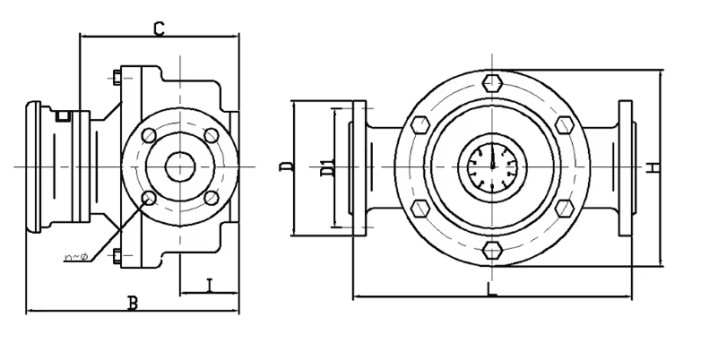
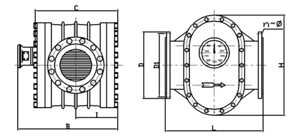
All linear dimensions below are in millimetres (mm). N is the number of bolt holes and Ø is the bolt-hole diameter. Click each drawing to view its full-size image.
DN10 to DN50 and DN65 DN80

DN100

DN150 and DN200

Overall Dimensions
| DN | L | H | B | C | I |
|---|
| 10 | 170 | 100 | 218 | 140 | 45 |
|---|
| 15 | 200 | 120 | 238 | 160 | 48 |
|---|
| 20 | 230 | 150 | 243 | 165 | 58 |
|---|
| 25 | 260 | 182 | 246 | 168 | 64 |
|---|
| 40 | 265 | 182 | 282 | 204 | 77 |
|---|
| 50 | 265 | 182 | 291 | 213 | 92 |
|---|
| 65 | 350 | 255 | 380 | 275 | 125 |
|---|
| 80 | 350 | 255 | 380 | 275 | 125 |
|---|
| 100 | 515 | 418 | 468 | 338 | 131 |
|---|
| 150 | 540 | 510 | 557 | 377 | 210 |
|---|
| 200 | 650 | 650 | 624 | 436 | 247 |
|---|
Flange and Bolt Dimensions
| DN | D | D1 | N | Ø |
|---|
| 10 | 90 | 60 | 4 | 14 |
|---|
| 15 | 95 | 65 | 4 | 14 |
|---|
| 20 | 105 | 75 | 4 | 14 |
|---|
| 25 | 115 | 85 | 4 | 14 |
|---|
| 40 | 150 | 110 | 4 | 18 |
|---|
| 50 | 165 | 125 | 4 | 18 |
|---|
| 65 | 185 | 145 | 4 | 18 |
|---|
| 80 | 200 | 160 | 8 | 18 |
|---|
| 100 | 220 | 180 | 8 | 18 |
|---|
| 150 | 285 | 240 | 8 | 23 |
|---|
| 200 | 340 | 295 | 12 | 23 |
|---|
Flange basis: Flange dimensions are based on a pressure rating of 1.6 MPa. Overall length and flange dimensions can be customized.
High-temperature version: For DN15–DN50, add 100 mm to dimension B for the thermal extension tube. This allowance does not apply to the other sizes listed above.
Selection and Ordering
Provide the liquid name, viscosity at operating temperature, minimum and maximum flow, pipe diameter, operating pressure and temperature, flange standard, preferred power supply and required output. The high-viscosity and high-temperature versions should be selected for the corresponding service conditions. Confirm the applicable configuration with ADDA before ordering.