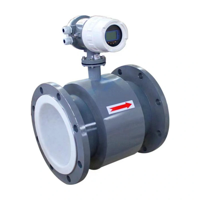
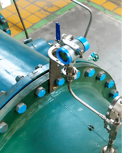
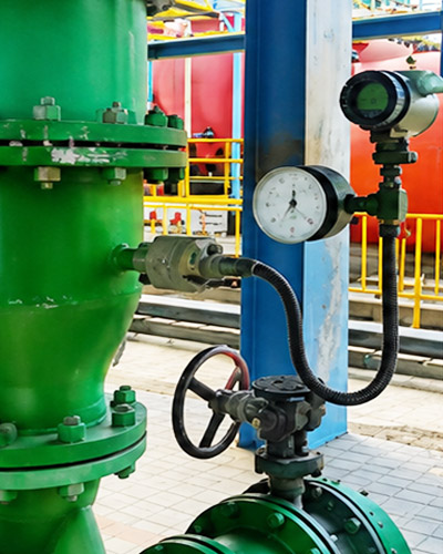
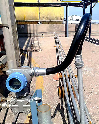
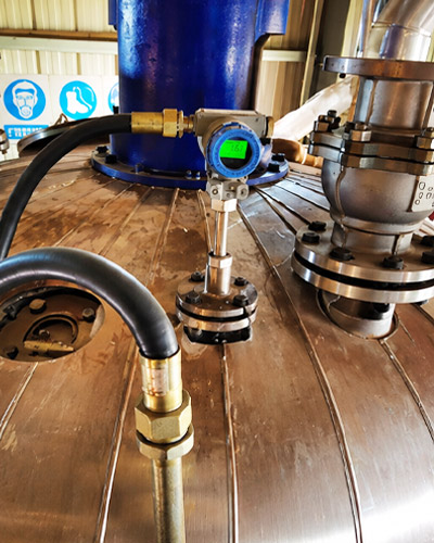
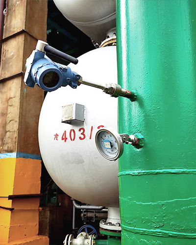
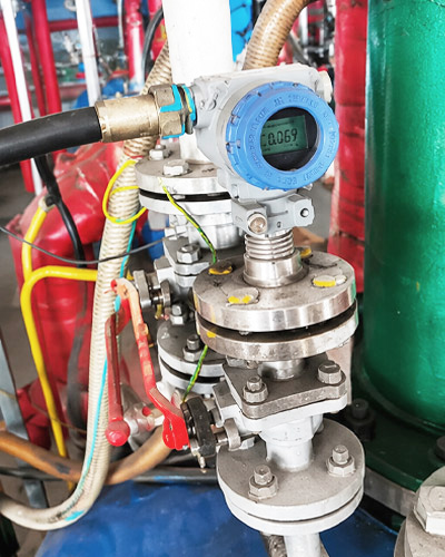
مقياس التدفق الكتلي كوريوليس لقياس التدفق الكتلي المباشر مع قياس الكثافة ودرجة الحرارة. تتوفر تكوينات متكاملة وجهاز إرسال عن بعد، مع تحديد أحجام المستشعر والاتصال لتناسب نطاق التدفق المطلوب.
شهادات التأهيل الرسمية
نحن حاصلون على شهادة الجودة ISO، ومؤهلات المؤسسات الوطنية عالية التقنية، والموافقة على نوع أداة القياس الصينية، وشهادات مقاومة الانفجار والسلامة لدعم جودة المنتج الموثوقة.
الهندسة المخصصة
مواد قابلة للتكوين، واتصالات، وإشارات، وشاشات عرض، وحلول تثبيت لبيئات العمليات المختلفة.
The ADDA-FL-ZL directly measures mass flow using the Coriolis effect. It also measures density and temperature, with display functions for mass flow, totalized mass, volumetric flow and totalized volume. Integral and remote transmitter arrangements are available.
سمات
Direct mass-flow measurement without conversion from intermediate volumetric measurements.
Simultaneous measurement of flow, density and temperature.
Two individually configurable signal outputs for the measured variables.
A turndown ratio of up to 20:1 is listed in the product features; range-table performance conditions are shown below.
Loop self-diagnostics to support fault finding.
Measurement Principle
Fluid passes through a vibrating measuring tube. The resulting Coriolis force produces a measurable response related to mass flow. Density is derived from the tube’s resonant behaviour, with temperature compensation for changes in tube stiffness.
Coriolis measurement principle
المواصفات الفنية
معلمة
تخصيص
Accuracy options
±0.15%, ±0.2%, ±0.5% or ±1.0%, depending on the ordered configuration
Repeatability
±0.05%
Density accuracy
±0.5 kg/m³
Temperature accuracy
±0.2°C; the parameter table gives a measurement interval of −240°C to +350°C
Nominal connection sizes
DN10–DN300
Pressure range
1–10 MPa, depending on the ordered configuration
Relative humidity
≤95%
مصدر طاقة
220 VAC ±10%, 50 Hz, or 24 VDC ±5%
Signal outputs
Pulse; 4–20 mA with optional HART; Modbus RTU RS485
Displayed variables
Mass flow, totalized mass, volumetric flow, totalized volume, density and temperature
Enclosure protection
IP67
The measurement temperature interval is not a universal operating rating for every configuration. Select the installation form, tube material and temperature version for the application. The catalogue includes homogeneous fluids and high-viscosity media such as honey and oil slurry; discuss the actual medium and operating conditions when selecting a model.
Mass Flow Ranges
Rated flow, maximum flow and zero stability are in kg/h. The complete model designation is ADDA-FL-ZL followed by the sensor size code A01–A15.
Mass flow ranges — connection sizes and rated flow
Sensor size
Connection sizes
Rated flow kg/h
A01
DN10/DN15/DN20/DN25
19
A02
DN10/DN15/DN20/DN25
96
A03
DN10/DN15/DN20/DN25
270
A04
DN15/DN20/DN25
520
A05
DN15/DN20/DN25/DN32
3800
A06
DN20/DN25/DN32/DN40
6500
A07
DN25/DN32/DN40/DN50
10500
A08
DN40/(DN50)/DN65
24000
A09
DN40/(DN50)/DN65/DN80
55000
A10
DN80/DN100/DN125
100000
A11
DN80/DN100/DN125/DN150
158000
A12
DN100/DN125/DN150
290000
A13
DN150/DN200/DN250
462000
A14
DN200/DN250/DN300
950000
A15
DN200/DN250/DN300
1600000
Mass flow ranges — maximum flow and zero stability
Sensor size
Maximum flow kg/h
Zero stability kg/h
A01
28
0.0014
A02
110
0.0055
A03
310
0.0155
A04
740
0.037
A05
5400
0.270
A06
9500
0.475
A07
15000
0.75
A08
34000
1.7
A09
75000
3.75
A10
140000
7.00
A11
225000
11.25
A12
403000
20.15
A13
652000
32.60
A14
1550000
77.50
A15
2500000
125.00
Within a 30:1 turndown ratio, the range table specifies mass-flow error of ±0.2%, mass-flow repeatability of ±0.05%, and volumetric-flow error of ±0.25%. Confirm these performance values for the selected accuracy option.
PN10, PN16, PN25, PN40, PN63 or PN100; confirm the applicable flange class and standard
Sealing faces
RF, M, T, RJ or a custom arrangement
Electrical entries
M20 × 1.5 or 1/2 NPT
خيار المنطقة الخطرة
Flameproof option listed as Exdb IIC T6 Gb, or a non-explosion-protected configuration. Confirm the actual marking and supporting documentation for the ordered model.
Dimensions A01–A15
All dimensions are in millimetres. Dimension A can be customized.
Remote transmitter
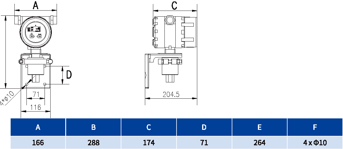
Remote transmitter dimensional drawing
Remote transmitter dimensions
A
B
C
D
E
F
166
288
174
71
264
4 × Ø10
Remote sensor dimensions
Remote sensor dimensional drawing A B C D E2
Remote sensors — connection sizes and A
Sensor size
Connection sizes
A
A01
DN10/DN15/DN20/DN25
343–353
A02
DN10/DN15/DN20/DN25
343–353
A03
DN10/DN15/DN20/DN25
343–353
A04
DN15/DN20/DN25
381–405
A05
DN15/DN20/DN25/DN32
433–461
A06
DN20/DN25/DN32/DN40
441–461
A07
DN25/DN32/DN40/DN50
528–548
A08
DN40/(DN50)/DN65
558–578
A09
DN40/(DN50)/DN65/DN80
509–529
A10
DN80/DN100/DN125
620–660
A11
DN80/DN100/DN125/DN150
759–799
A12
DN100/DN125/DN150
846–892
A13
DN150/DN200/DN250
984–1230
A14
DN200/DN250/DN300
1024–1054
A15
DN200/DN250/DN300
1043–1129
Remote sensors — B C D E2
Sensor size
B
C
D
E2
A01
183
216
54
306
A02
183
216
54
306
A03
183
216
54
306
A04
211
220
60
334
A05
283
302
70
416
A06
295
301
70
428
A07
350
370
85
493
A08
426
406
86
569
A09
574
420
140
687
A10
521
718
530
850
A11
813
630
206
957
A12
896
720
240
1052
A13
952
870
340
1126
A14
1219
810
348
1419
A15
1338
878
460
1551
Integral dimensions
Integral mass flow meter dimensional drawing A B C D E1 F
Integral meters — connection sizes and A
Sensor size
Connection sizes
A
A01
DN10/DN15/DN20/DN25
343–353
A02
DN10/DN15/DN20/DN25
343–353
A03
DN10/DN15/DN20/DN25
343–353
A04
DN15/DN20/DN25
381–405
A05
DN15/DN20/DN25/DN32
433–461
A06
DN20/DN25/DN32/DN40
441–461
A07
DN25/DN32/DN40/DN50
528–548
A08
DN40/(DN50)/DN65
558–578
A09
DN40/(DN50)/DN65/DN80
509–529
A10
DN80/DN100/DN125
620–660
A11
DN80/DN100/DN125/DN150
759–799
A12
DN100/DN125/DN150
846–892
A13
DN150/DN200/DN250
984–1230
A14
DN200/DN250/DN300
1024–1054
A15
DN200/DN250/DN300
1043–1129
Integral meters — B C D
Sensor size
B
C
D
A01
183
216
54
A02
183
216
54
A03
183
216
54
A04
211
220
60
A05
283
302
70
A06
295
301
70
A07
350
370
85
A08
426
406
86
A09
574
420
140
A10
521
718
530
A11
813
630
206
A12
896
720
240
A13
952
870
340
A14
1219
810
348
A15
1338
878
460
Integral meters — E1 and F
Sensor size
E1
F
A01
451
173
A02
451
173
A03
451
173
A04
479
173
A05
561
173
A06
573
173
A07
638
173
A08
714
173
A09
832
173
A10
995
173
A11
1102
173
A12
1198
173
A13
1271
173
A14
1564
173
A15
1696
173
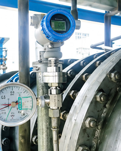
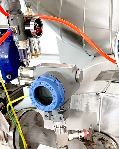
إرشادات التثبيت
Application
Recommended orientation
Liquids
Horizontal pipe with the sensor housing below the pipe to limit trapped air
Gases
Horizontal pipe with the sensor housing above the pipe to limit condensate accumulation
Liquids or solid–liquid mixtures
Vertical pipe arrangement to limit particle accumulation
Keep the sensor away from pumps and other sources of mechanical pipe vibration, as well as large motors, transformers and other electromagnetic interference sources.
For liquid measurement, keep the measuring tubes full and maintain suitable back pressure. Select a low point in the pipeline where appropriate.
Account for thermal expansion and pipe deformation; do not position the meter close to a pipeline expansion joint.
Connect the sensor and pipe flanges coaxially without installation stress.
Provide shutoff valves upstream and downstream. Secure the pipe and valves to a stable foundation with suitable supports.
Do not use the sensor housing to support the sensor, pipe, valves or pumps. The sensor housing should remain freely suspended after installation.
يرجى تقديم الوسيط المقاس ونطاق القياس ودرجة حرارة العملية وضغط العملية ونوع الاتصال وإشارة الخرج وإمدادات الطاقة وبيئة التثبيت وطريقة الاتصال إذا كانت المراقبة عن بعد مطلوبة.
نعم. يمكن لفريقنا المساعدة في التوصية بتكوين مناسب للأداة بعد مراجعة شروط التطبيق الخاصة بك، بما في ذلك متطلبات المتوسط والمدى والاتصال وإشارة الخرج والتركيب.
تعتمد المهلة الزمنية على نوع المنتج والكمية ومتطلبات التخصيص واحتياجات إصدار الشهادات. عادةً ما يكون للمنتجات القياسية وقت تسليم أقصر، بينما قد تتطلب النماذج المخصصة وقتًا إضافيًا للإنتاج.