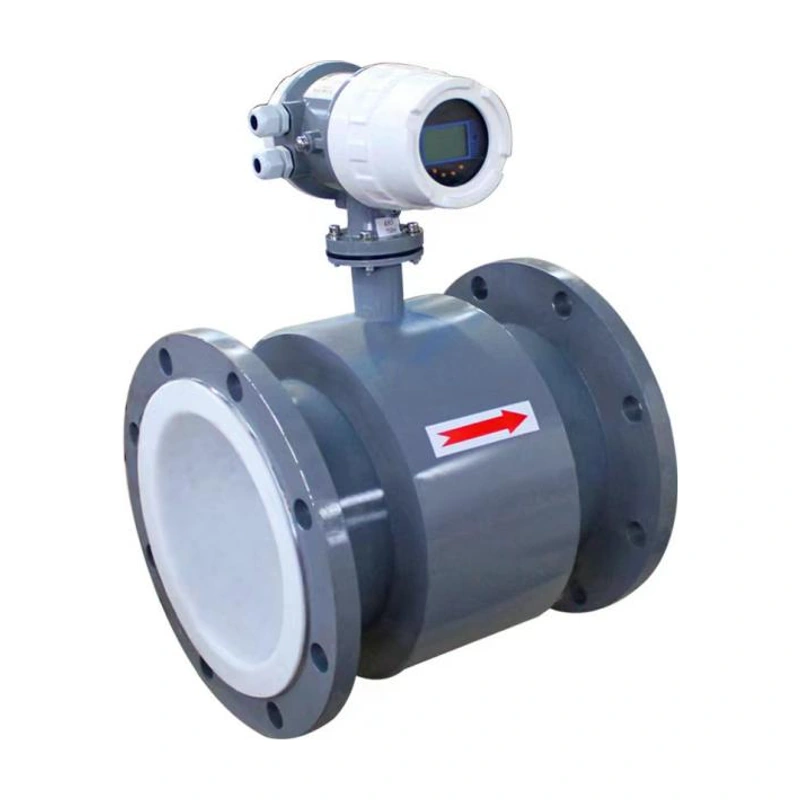
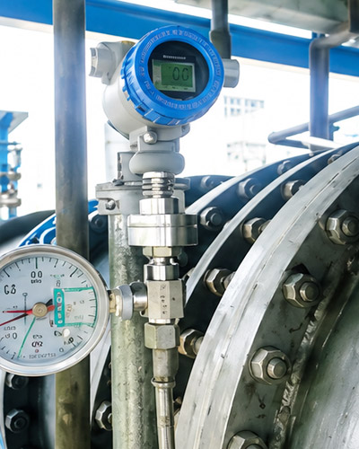
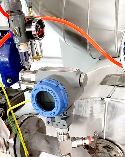
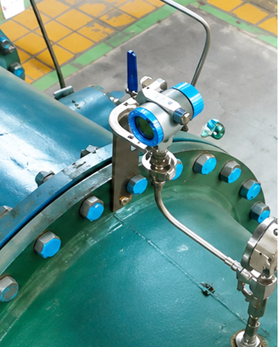
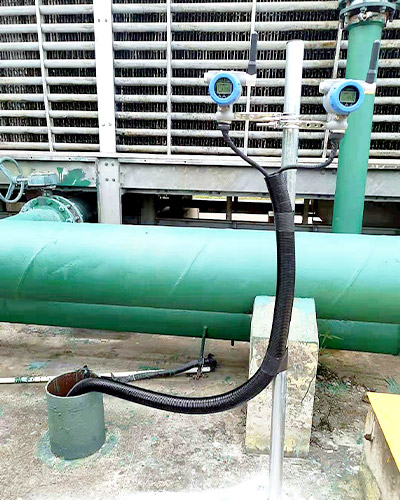
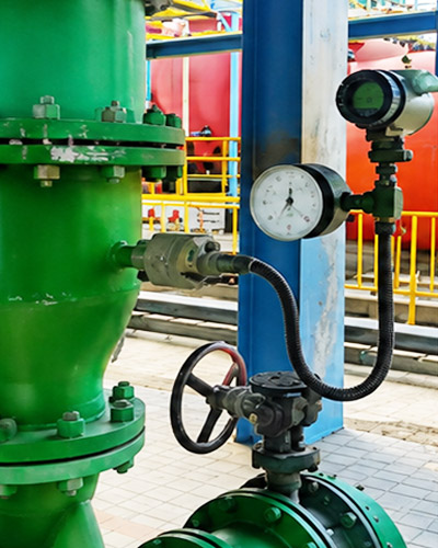
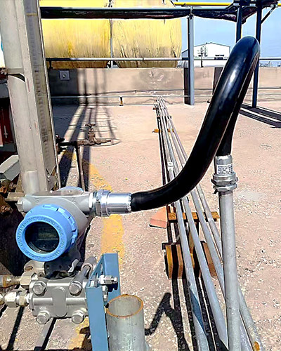
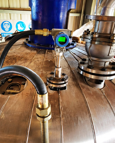
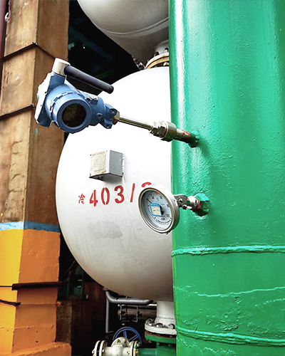
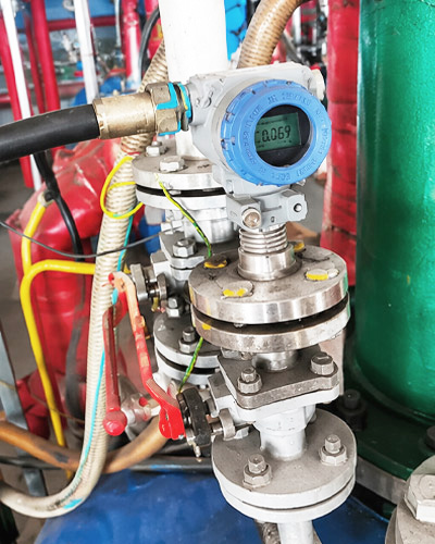
مقياس تدفق دوامي مضمن للسوائل أحادية الطور والغازات الجافة والبخار المتوافقة. تتوفر إصدارات ذات حواف ورقاقة DN15 وDN300، مع خيارات درجة حرارة المعالجة حتى +350° مئوية ودرجة حرارة اختيارية أو تعويض درجة الحرارة والضغط.
شهادات التأهيل الرسمية
نحن حاصلون على شهادة الجودة ISO، ومؤهلات المؤسسات الوطنية عالية التقنية، والموافقة على نوع أداة القياس الصينية، وشهادات مقاومة الانفجار والسلامة لدعم جودة المنتج الموثوقة.
الهندسة المخصصة
مواد قابلة للتكوين، واتصالات، وإشارات، وشاشات عرض، وحلول تثبيت لبيئات العمليات المختلفة.
The ADDA-FL-WJ is an inline vortex flow meter based on the Kármán vortex shedding principle. It measures the flow of compatible single-phase liquids, dry gases and steam. Depending on the selected compensation configuration, the transmitter can indicate operating volumetric flow, normalized volumetric flow or calculated mass flow.
Typical applications include petroleum processing, chemical production, power generation and industrial heating. Select the meter size, materials, temperature range and compensation method to match the medium and operating conditions.
سمات
No moving parts in the measuring body.
Flanged and wafer connections from DN15 to DN300.
304 or 316 stainless steel body and probe options.
Temperature versions up to +250°C or +350°C.
Frequency, scaled pulse, two-wire 4–20 mA, HART and Modbus RTU over RS485 options.
Configurations without compensation, with temperature compensation, or with temperature and pressure compensation.
مبدأ التشغيل
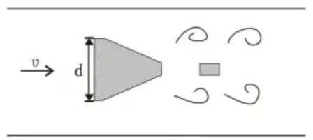
A fixed bluff body in the flow path generates alternating vortices downstream. Within the specified Reynolds-number range, the vortex shedding frequency is proportional to flow velocity. A piezoelectric or capacitive pickup detects the resulting pressure fluctuations, and the transmitter converts their frequency into flow.
f = St × v / d, where f is vortex shedding frequency, St is the Strouhal number, v is flow velocity and d is the bluff-body width. Volumetric flow is derived from the calibrated meter factor K; frequency and volume units must be consistent when applying Q = f / K.
Kármán vortex shedding principle
المواصفات الفنية
معلمة
تخصيص
Model
ADDA-FL-WJ
Suitable media
Compatible single-phase liquids, dry gases and steam
الحجم الاسمي
DN15–DN300
Process connections
Flanged or wafer
Body material
304 or 316 stainless steel
Probe material
304 or 316 stainless steel
Process temperature
Standard/medium-temperature version: −40 to +250°C; high-temperature version: −40 to +350°C
Nominal pressure
PN10–PN63, depending on configuration
Accuracy classes
1.0 or 1.5 for gas and liquid service
Repeatability
Better than one third of the absolute maximum permissible error for the selected accuracy class
Ambient temperature
−10 to +55°C
Relative humidity
5–90%
Atmospheric pressure
86–106 kPa
مصدر طاقة
24 V DC nominal (18–29 V DC); 3.6 V lithium battery; or 24 V DC with 3.6 V battery, depending on configuration
Required compensation, output and power options must be selected together. Operating limits depend on medium density, Reynolds number, meter size and process conditions. The catalogue specifies a minimum Reynolds number of 5,000; confirm the selected operating range before ordering.
Liquid Flow Sizing
The tables show the lower measurable flow for different liquid densities. All flow values are in m³/h. The reference-flow column is reproduced for sizing comparison; it is not a normalized gas-volume unit.
Liquid minimum measurable flow at the stated density (m³/h) — Part 1 of 2
Size
500 kg/m³
600 kg/m³
700 kg/m³
DN15
0.57
0.52
0.48
DN20
0.85
0.77
0.72
DN25
1.27
1.16
1.08
DN32
2.12
1.94
1.79
DN40
3.25
2.97
2.75
DN50
4.95
4.52
4.18
DN65
8.49
7.75
7.17
DN80
13
12
11
DN100
20
18
17
DN125
31
28
26
DN150
45
41
38
DN200
81
74
68
DN250
126
115
106
DN300
180
164
152
Liquid minimum measurable flow at the stated density (m³/h) — Part 2 of 2
Size
800 kg/m³
900 kg/m³
Reference flow
DN15
0.45
0.42
4
DN20
0.67
0.63
6
DN25
1.01
0.95
9
DN32
1.68
1.58
15
DN40
2.57
2.42
23
DN50
3.91
3.69
35
DN65
6.71
6.32
60
DN80
10
9.49
90
DN100
16
15
140
DN125
25
23
220
DN150
36
34
320
DN200
64
60
570
DN250
100
94
890
DN300
142
134
1270
Liquid minimum measurable flow at the stated density (m³/h) — Part 1 of 2
Size
1000 kg/m³
1200 kg/m³
1400 kg/m³
DN15
0.4
0.37
0.34
DN20
0.6
0.55
0.51
DN25
0.9
0.82
0.76
DN32
1.5
1.37
1.27
DN40
2.3
2.10
1.94
DN50
3.5
3.20
2.96
DN65
6
5.48
5.07
DN80
9
8.22
7.61
DN100
14
13
12
DN125
22
20
19
DN150
32
29
27
DN200
57
52
48
DN250
89
81
75
DN300
127
116
107
Liquid minimum measurable flow at the stated density (m³/h) — Part 2 of 2
Size
1600 kg/m³
1800 kg/m³
Reference flow
DN15
0.32
0.30
4
DN20
0.47
0.45
6
DN25
0.71
0.67
9
DN32
1.19
1.12
15
DN40
1.82
1.71
23
DN50
2.77
2.61
35
DN65
4.74
4.47
60
DN80
7.12
6.71
90
DN100
—
10
140
DN125
17
16
220
DN150
25
24
320
DN200
45
42
570
DN250
70
66
890
DN300
100
95
1270
“—” means the value must be confirmed on request.
Gas Flow Sizing
The gas lower limit depends strongly on density at the measurement conditions. Use the actual gas composition, pressure and temperature when selecting a size and compensation configuration.
Gas minimum measurable flow at the stated density (m³/h) — Part 1 of 3
Size
0.5 kg/m³
0.8 kg/m³
1.2 kg/m³
DN15
9
7
5
DN20
9
7
5.5
DN25
14
11
9
DN32
23
18
15
DN40
34
27
22
DN50
54
43
35
DN65
93
74
60
DN80
140
110
90
DN100
217
172
140
DN125
342
270
220
DN150
466
368
300
DN200
854
675
550
DN250
1397
1105
900
DN300
2018
1595
1300
Gas minimum measurable flow at the stated density (m³/h) — Part 2 of 3
Size
2.4 kg/m³
3.6 kg/m³
4.8 kg/m³
DN15
3.5
2.9
2.5
DN20
3.9
3.2
2.8
DN25
6.4
5.2
4.5
DN32
11
8.7
7.5
DN40
16
13
11
DN50
25
20
18
DN65
43
35
30
DN80
64
52
45
DN100
99
81
70
DN125
156
127
110
DN150
213
174
150
DN200
390
318
276
DN250
638
521
451
DN300
921
752
651
Gas minimum measurable flow at the stated density (m³/h) — Part 3 of 3
Size
Reference flow
DN15
30
DN20
67
DN25
90
DN32
150
DN40
220
DN50
350
DN65
600
DN80
900
DN100
1400
DN125
2200
DN150
3000
DN200
5500
DN250
9000
DN300
13000
Gas minimum measurable flow at the stated density (m³/h) — Part 1 of 3
Size
6.0 kg/m³
7.2 kg/m³
8.4 kg/m³
DN15
2.2
2.0
1.9
DN20
2.5
2.3
2.1
DN25
4.0
3.7
3.4
DN32
6.7
6.1
5.7
DN40
9.9
9.0
8.3
DN50
16
14
13
DN65
27
25
23
DN80
40
37
34
DN100
63
57
53
DN125
99
90
83
DN150
134
123
114
DN200
246
225
208
DN250
403
368
341
DN300
583
532
492
Gas minimum measurable flow at the stated density (m³/h) — Part 2 of 3
Size
9.6 kg/m³
12.0 kg/m³
20.0 kg/m³
DN15
1.8
1.6
1.2
DN20
1.9
1.7
1.4
DN25
3.2
2.9
2.2
DN32
5.3
4.8
3.7
DN40
7.8
7.0
5.4
DN50
12
11.1
8.6
DN65
21
19
15
DN80
32
29
22
DN100
50
44
34
DN125
78
72
54
DN150
106
95
74
DN200
195
174
135
DN250
319
285
221
DN300
461
412
319
Gas minimum measurable flow at the stated density (m³/h) — Part 3 of 3
Size
Reference flow
DN15
30
DN20
67
DN25
90
DN32
150
DN40
220
DN50
350
DN65
600
DN80
900
DN100
1400
DN125
2200
DN150
3000
DN200
5500
DN250
9000
DN300
13000
Selection Options
اختيار
شفرة
خيار
Connection
F1
Flanged
Connection
F2
Wafer
Compensation
N0
Without temperature or pressure compensation
Compensation
WD
Temperature compensation
Compensation
WY
Temperature and pressure compensation
Temperature version
C
−40 to +250°C
Temperature version
G
−40 to +350°C
Probe material
4
304 ستانلس ستيل
Probe material
6
316 stainless steel
Body material
4
304 ستانلس ستيل
Body material
6
316 stainless steel
إخراج
P
Frequency
إخراج
M
Scaled pulse
إخراج
F
سلكين 4 · 20 مللي أمبير
إخراج
H
Two-wire 4–20 mA + HART
إخراج
R
Modbus RTU over RS485
توصيل كهربائي
M
M20 × 1.5
توصيل كهربائي
N
1/2 NPT
Hazardous-area requirement
N
Non-explosion-protected version
Hazardous-area requirement
D
Flameproof version; confirm marking and applicable certification for the supplied configuration
Specify the nominal size, pressure rating, process medium, operating flow, pressure and temperature, required accuracy and power supply. Confirm compatible options and the final configuration before ordering.
أبعاد
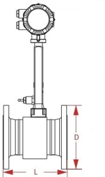
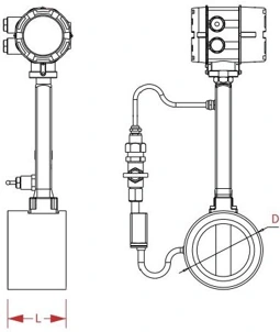
Dimensions are in millimetres unless otherwise stated. Confirm the final drawing and pressure rating for the ordered meter.
Flanged Version
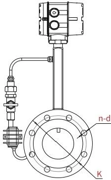
Flanged version, side viewFlanged version, end view
PN10 flanged dimensions — Part 1 of 3
DN
Rating
Standard L
Available L range
15
PN10
200
200–250
20
PN10
200
200–250
25
PN10
200
200–250
32
PN10
200
200–250
40
PN10
200
200–250
50
PN10
200
200–250
65
PN10
200
200–250
80
PN10
200
200–250
100
PN10
220
220–250
125
PN10
220
220–280
150
PN10
220
220–280
200
PN10
270
270–300
250
PN10
310
310–350
300
PN10
350
350–350
PN10 flanged dimensions — Part 2 of 3
DN
D
K
n–d holes
15
95
65
4-14
20
105
75
4-14
25
115
85
4-14
32
140
100
4-18
40
150
110
4-18
50
165
125
4-18
65
185
145
8-18
80
200
160
8-18
100
220
180
8-18
125
250
210
8-18
150
285
240
8-22
200
340
295
12-22
250
405
355
12-26
300
460
410
12-26
PN10 flanged dimensions — Part 3 of 3
DN
Bolt size
15
M12×60
20
M12×60
25
M12×60
32
M16×70
40
M16×70
50
M16×70
65
M16×70
80
M16×70
100
M16×70
125
M16×70
150
M20×100
200
M20×100
250
M24×100
300
M24×100
The listed flange dimensions are for PN10. Other pressure ratings require a confirmed dimensional drawing. K is the bolt-circle diameter; n–d states the number and diameter of bolt holes.
Wafer Version
Wafer version dimensions
DN
Length L
Outside diameter D
Connecting pipe OD × wall thickness
15
85
87
Ø18 × 2
20
85
87
Ø25 × 3
25
85
87
Ø32 × 3
32
85
87
Ø38 × 3
40
85
100
Ø45 × 3
50
85
100
Ø57 × 3.5
65
90
120
—
80
95
136
—
100
110
149
Ø108 × 4
125
110
175
Ø133 × 4
150
130
203
Ø159 × 4.5
200
150
259
Ø219 × 6
250
180
312
Ø273 × 6.5
300
200
363
Ø325 × 8
“—” means the connecting-pipe specification must be confirmed on request.
Installation Requirements
Layout or component
Requirement
Reducer, expander or elbow upstream
Provide at least 15D of straight pipe upstream and 5D downstream. D is the nominal internal diameter of the meter.
Control valve downstream
Install control valves downstream where possible, retaining at least 5D between the meter and valve. Upstream straight length depends on preceding fittings.
Control valve upstream
If unavoidable, provide at least 25D upstream and 5D downstream.
Piston or plunger pump
Use a suitable upstream accumulator or pulsation damper to reduce liquid pulsations.
Pulsating gas or liquid flow
Pulsation from reciprocating pumps, blowers or compressors can disturb measurement. Select an upstream damping arrangement and verify the layout.
Tee branch with intermittent flow
A closed downstream valve can leave the meter exposed to pressure pulsations from the live branch. An appropriately located upstream isolation valve may be needed to isolate the inactive meter branch.
Pressure tapping
Locate the pressure measurement point 3–5D downstream of the meter.
Temperature tapping
Locate the temperature measurement point 6–8D downstream of the meter.
Vibration
Choose a low-vibration location; support the pipeline where necessary.
Pipe bore
The catalogue specifies a connecting-pipe internal diameter 1–5 mm larger than the meter bore. Confirm the selected mating pipe dimensions.
Assembly
Align the meter and pipe concentrically. Flush pipework to remove welding debris and other foreign material before installing the meter.
Gas and Steam Service
Prevent condensate from collecting in the measuring section. Vertical mounting or a suitable high-point arrangement in horizontal piping can help avoid liquid accumulation. Do not locate the meter at the bottom of a U-shaped section where condensate can collect.
Liquid Service
Keep the measuring tube completely full. Upward flow is preferred in vertical pipework. Where downward flow is used, position the meter below the downstream pipe elevation so the measuring section remains flooded. Avoid high points where gas can collect, and place the meter upstream of a control valve where a pressure drop could create bubbles.
Entrained gas, stratified flow and other mixed-phase conditions can impair accuracy or prevent reliable measurement. Confirm single-phase service and a suitable installation layout before commissioning.
يرجى تقديم الوسيط المقاس ونطاق القياس ودرجة حرارة العملية وضغط العملية ونوع الاتصال وإشارة الخرج وإمدادات الطاقة وبيئة التثبيت وطريقة الاتصال إذا كانت المراقبة عن بعد مطلوبة.
نعم. يمكن لفريقنا المساعدة في التوصية بتكوين مناسب للأداة بعد مراجعة شروط التطبيق الخاصة بك، بما في ذلك متطلبات المتوسط والمدى والاتصال وإشارة الخرج والتركيب.
تعتمد المهلة الزمنية على نوع المنتج والكمية ومتطلبات التخصيص واحتياجات إصدار الشهادات. عادةً ما يكون للمنتجات القياسية وقت تسليم أقصر، بينما قد تتطلب النماذج المخصصة وقتًا إضافيًا للإنتاج.