
SKU ADDA-FL-KL Categoría

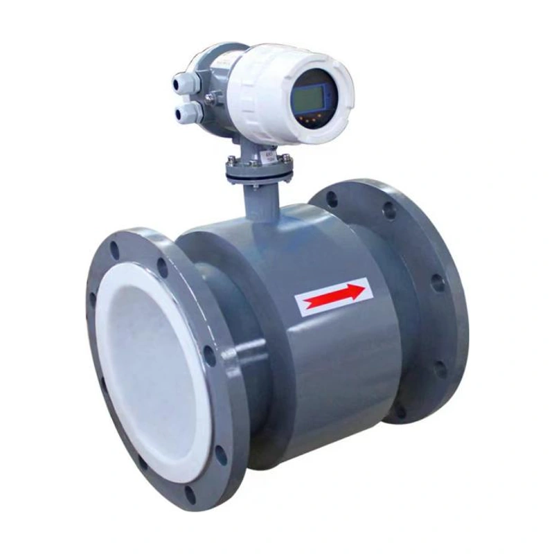
Medidor de flujo másico ADDA-FL-ZL Coriolis

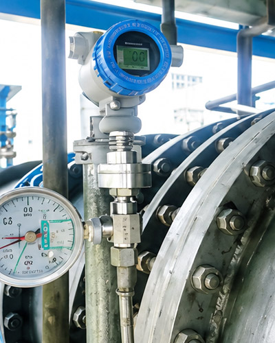
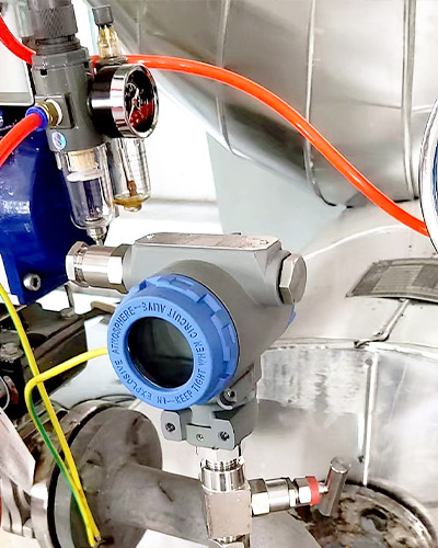
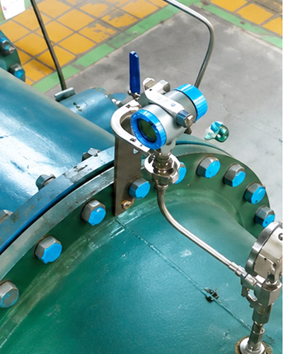
Medidor de flujo másico Coriolis para medición directa de flujo másico con medición de densidad y temperatura. Se encuentran disponibles configuraciones de transmisor integral y remoto, con tamaños de sensor y conexión seleccionados para adaptarse al rango de flujo requerido.

Certificaciones de Calificación Autorizadas

Contamos con certificación de calidad ISO, calificación empresarial nacional de alta tecnología, aprobación de tipo de instrumento de medición de China y certificaciones de seguridad y a prueba de explosiones para respaldar una calidad confiable del producto.

Ingeniería personalizada

Materiales configurables, conexiones, señales, displays y soluciones de instalación para diferentes entornos de proceso.

Descripción general | Especificaciones | Rangos de flujo | Dimensiones | Instalación

Coriolis Mass Flow Measurement

The ADDA-FL-ZL directly measures mass flow using the Coriolis effect. It also measures density and temperature, with display functions for mass flow, totalized mass, volumetric flow and totalized volume. Integral and remote transmitter arrangements are available.

Características

  • Direct mass-flow measurement without conversion from intermediate volumetric measurements.
  • Simultaneous measurement of flow, density and temperature.
  • Two individually configurable signal outputs for the measured variables.
  • A turndown ratio of up to 20:1 is listed in the product features; range-table performance conditions are shown below.
  • Loop self-diagnostics to support fault finding.

Measurement Principle

Fluid passes through a vibrating measuring tube. The resulting Coriolis force produces a measurable response related to mass flow. Density is derived from the tube’s resonant behaviour, with temperature compensation for changes in tube stiffness.

Coriolis measuring tube vibration and force direction diagram
Coriolis measurement principle

Especificaciones técnicas

ParámetroEspecificación
Opciones de precisión±0.15%, ±0.2%, ±0.5% or ±1.0%, depending on the ordered configuration
Repetibilidad±0.05%
Density accuracy±0.5 kg/m³
Temperature accuracy±0.2°C; the parameter table gives a measurement interval of −240°C to +350°C
Nominal connection sizesDN10–DN300
Pressure range1–10 MPa, depending on the ordered configuration
Humedad relativa≤95%
Fuente de alimentación220 VAC ±10%, 50 Hz, or 24 VDC ±5%
Salidas de señalPulse; 4–20 mA with optional HART; Modbus RTU RS485
Displayed variablesMass flow, totalized mass, volumetric flow, totalized volume, density and temperature
Enclosure protectionIP67

The measurement temperature interval is not a universal operating rating for every configuration. Select the installation form, tube material and temperature version for the application. The catalogue includes homogeneous fluids and high-viscosity media such as honey and oil slurry; discuss the actual medium and operating conditions when selecting a model.

Mass Flow Ranges

Rated flow, maximum flow and zero stability are in kg/h. The complete model designation is ADDA-FL-ZL followed by the sensor size code A01–A15.

Mass flow ranges — connection sizes and rated flow
Sensor sizeConnection sizesRated flow kg/h
A01DN10/DN15/DN20/DN2519
A02DN10/DN15/DN20/DN2596
A03DN10/DN15/DN20/DN25270
A04DN15/DN20/DN25520
A05DN15/DN20/DN25/DN323800
A06DN20/DN25/DN32/DN406500
A07DN25/DN32/DN40/DN5010500
A08DN40/(DN50)/DN6524000
A09DN40/(DN50)/DN65/DN8055000
A10DN80/DN100/DN125100000
A11DN80/DN100/DN125/DN150158000
A12DN100/DN125/DN150290000
A13DN150/DN200/DN250462000
A14DN200/DN250/DN300950000
A15DN200/DN250/DN3001600000
Mass flow ranges — maximum flow and zero stability
Sensor sizeMaximum flow kg/hZero stability kg/h
A01280.0014
A021100.0055
A033100.0155
A047400.037
A0554000.270
A0695000.475
A07150000.75
A08340001.7
A09750003.75
A101400007.00
A1122500011.25
A1240300020.15
A1365200032.60
A14155000077.50
A152500000125.00

Within a 30:1 turndown ratio, the range table specifies mass-flow error of ±0.2%, mass-flow repeatability of ±0.05%, and volumetric-flow error of ±0.25%. Confirm these performance values for the selected accuracy option.

Opciones de configuración

ArtículoOpciones disponibles
Transmitter arrangementIntegral o remoto
High-temperature arrangementRemote, +80°C to +204°C
Low-temperature arrangementRemote, −240°C to −40°C
Process-connection and measuring-tube materials316L, 904L, titanium, C4 steel, Hastelloy C-276, duplex 2205 or tantalum
Flange standards listedHG/T 20592-2009, HG/T 20615-2010 or ANSI B16.5
Pressure designations listedPN10, PN16, PN25, PN40, PN63 or PN100; confirm the applicable flange class and standard
Sealing facesRF, M, T, RJ or a custom arrangement
Entradas eléctricasM20×1,5 sau 1/2 NPT
Opción de zona peligrosaFlameproof option listed as Exdb IIC T6 Gb, or a non-explosion-protected configuration. Confirm the actual marking and supporting documentation for the ordered model.

Dimensions A01–A15

All dimensions are in millimetres. Dimension A can be customized.

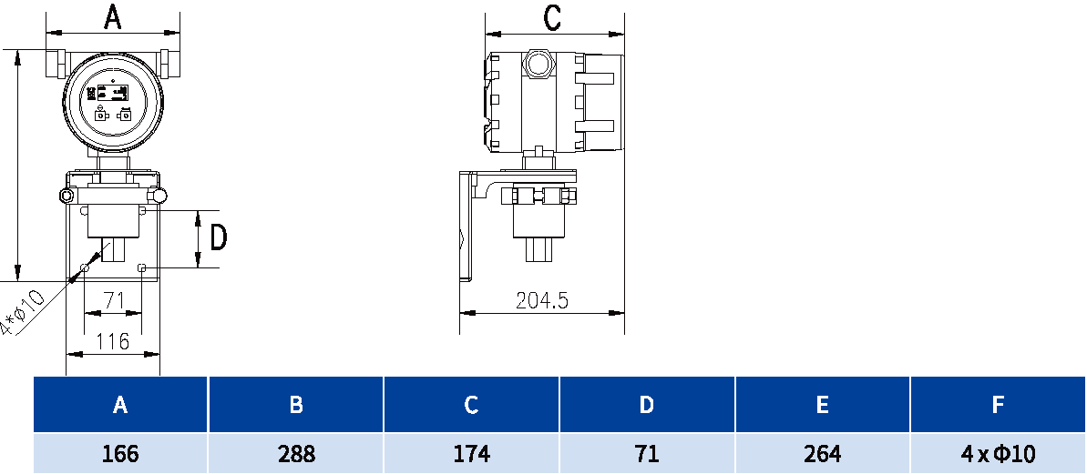
Remote transmitter

Remote transmitter dimensional drawing
Remote transmitter dimensions
ABCDEF
166288174712644 × Ø10

Dimensiones del sensor remoto

Remote sensor dimensional drawing A B C D E2
Remote sensors — connection sizes and A
Sensor sizeConnection sizesA
A01DN10/DN15/DN20/DN25343–353
A02DN10/DN15/DN20/DN25343–353
A03DN10/DN15/DN20/DN25343–353
A04DN15/DN20/DN25381–405
A05DN15/DN20/DN25/DN32433–461
A06DN20/DN25/DN32/DN40441–461
A07DN25/DN32/DN40/DN50528–548
A08DN40/(DN50)/DN65558–578
A09DN40/(DN50)/DN65/DN80509–529
A10DN80/DN100/DN125620–660
A11DN80/DN100/DN125/DN150759–799
A12DN100/DN125/DN150846–892
A13DN150/DN200/DN250984–1230
A14DN200/DN250/DN3001024–1054
A15DN200/DN250/DN3001043–1129
Remote sensors — B C D E2
Sensor sizeBCDE2
A0118321654306
A0218321654306
A0318321654306
A0421122060334
A0528330270416
A0629530170428
A0735037085493
A0842640686569
A09574420140687
A10521718530850
A11813630206957
A128967202401052
A139528703401126
A1412198103481419
A1513388784601551

Integral dimensions

Integral mass flow meter dimensional drawing A B C D E1 F
Integral meters — connection sizes and A
Sensor sizeConnection sizesA
A01DN10/DN15/DN20/DN25343–353
A02DN10/DN15/DN20/DN25343–353
A03DN10/DN15/DN20/DN25343–353
A04DN15/DN20/DN25381–405
A05DN15/DN20/DN25/DN32433–461
A06DN20/DN25/DN32/DN40441–461
A07DN25/DN32/DN40/DN50528–548
A08DN40/(DN50)/DN65558–578
A09DN40/(DN50)/DN65/DN80509–529
A10DN80/DN100/DN125620–660
A11DN80/DN100/DN125/DN150759–799
A12DN100/DN125/DN150846–892
A13DN150/DN200/DN250984–1230
A14DN200/DN250/DN3001024–1054
A15DN200/DN250/DN3001043–1129
Integral meters — B C D
Sensor sizeBCD
A0118321654
A0218321654
A0318321654
A0421122060
A0528330270
A0629530170
A0735037085
A0842640686
A09574420140
A10521718530
A11813630206
A12896720240
A13952870340
A141219810348
A151338878460
Integral meters — E1 and F
Sensor sizeE1F
A01451173
A02451173
A03451173
A04479173
A05561173
A06573173
A07638173
A08714173
A09832173
A10995173
A111102173
A121198173
A131271173
A141564173
A151696173

Guía de instalación

ApplicationRecommended orientation
LiquidsHorizontal pipe with the sensor housing below the pipe to limit trapped air
GasesHorizontal pipe with the sensor housing above the pipe to limit condensate accumulation
Liquids or solid–liquid mixturesVertical pipe arrangement to limit particle accumulation
  • Keep the sensor away from pumps and other sources of mechanical pipe vibration, as well as large motors, transformers and other electromagnetic interference sources.
  • For liquid measurement, keep the measuring tubes full and maintain suitable back pressure. Select a low point in the pipeline where appropriate.
  • Account for thermal expansion and pipe deformation; do not position the meter close to a pipeline expansion joint.
  • Connect the sensor and pipe flanges coaxially without installation stress.
  • Provide shutoff valves upstream and downstream. Secure the pipe and valves to a stable foundation with suitable supports.
  • Do not use the sensor housing to support the sensor, pipe, valves or pumps. The sensor housing should remain freely suspended after installation.

Productos relacionados

Escaparate

Preguntas frecuentes

Encuentre respuestas rápidas sobre selección de productos, personalización, parámetros técnicos, entrega y soporte para instrumentos de medición industrial ADDA.

官网询盘

Proporcione el medio medido, el rango de medición, la temperatura del proceso, la presión del proceso, el tipo de conexión, la señal de salida, la fuente de alimentación, el entorno de instalación y el método de comunicación si se requiere monitoreo remoto.

Sí. ADDA puede proporcionar soluciones personalizadas basadas en rango de medición, conexión de proceso, material mojado, tipo de pantalla, protocolo de comunicación, método de instalación y entorno de trabajo.

Muchos instrumentos ADDA están disponibles con configuraciones a prueba de explosiones o intrínsecamente seguras. Confirme los requisitos de clasificación y certificación del sitio antes de la selección.

Sí. Nuestro equipo puede ayudarle a recomendar una configuración de instrumento adecuada después de revisar las condiciones de su aplicación, incluido el medio, el alcance, la conexión, la señal de salida y los requisitos de instalación.

El plazo de entrega depende del tipo de producto, la cantidad, los requisitos de personalización y las necesidades de certificación. Los productos estándar suelen tener un tiempo de entrega más corto, mientras que los modelos personalizados pueden requerir un tiempo de producción adicional.

Contáctenos para cooperación

官网询盘