The ADDA-FL-LX is a positive displacement flow meter for liquid metering across a wide viscosity range. The DN25–DN300 series uses paired helical rotors and offers standard, high-viscosity, high-temperature and jacketed configurations, with optional pulse, 4–20 mA, Modbus RTU RS485 and HART outputs.
Authoritative Qualification Certifications
We hold ISO quality certification, national high-tech enterprise qualification, China measuring instrument type approval, and explosion-proof and safety certifications to support reliable product quality.
Custom Engineering
Configurable materials, connections, signals, displays, and installation solutions for different process environments.
The ADDA-FL-LX is a positive displacement flow meter with two helical rotors. Liquid pressure drives the rotors and transfers measured volumes through enclosed chambers. Counting rotor revolutions provides total volume and instantaneous flow. The design supports smooth liquid delivery over a wide viscosity range and does not require a developed flow profile.
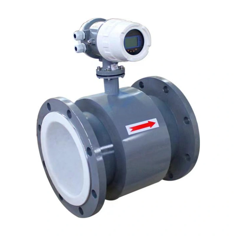
ADDA-FL-LX catalogue product illustration.
Features
Smooth operation with low noise and a design intended to avoid flow pulsation during continuous high-flow service.
High flow capacity for the nominal size with low pressure loss.
Accuracy of 0.5%, with 0.2% available as an option.
Standard and high-viscosity variants covering the viscosity bands listed in the flow tables.
Non-contact rotors reduce wear; confirm compatibility for the actual process liquid.
No upstream or downstream straight-pipe section is required.
High-temperature and jacketed configurations are available for suitable processes.
Operating Principle
A pair of specially shaped 45° helical rotors is installed in the measuring chamber. The inlet-to-outlet pressure difference drives the rotors, while the rotor surfaces and housing enclose fixed-volume pockets. Each revolution transfers eight chamber volumes from the inlet to the outlet. Magnetic or photoelectric sensing converts rotor motion into total volume and instantaneous flow rate.
V = 8 × V0 × n, where V is total measured volume, V0 is the volume of one measuring chamber and n is the number of rotor revolutions.
Technical Specifications
Parameter
Specification
Measured media
Clean liquids compatible with the selected materials, including oil, petroleum products, diesel, adhesives, emulsions, bitumen, resins, and acid or alkaline liquids
Nominal size
DN25–DN300
Ingress protection
IP66
Materials
SUS304 or SUS316L stainless steel
Power supply
24 V DC or 3.6 V lithium battery, depending on the configuration
Output options
4–20 mA, Modbus RTU RS485 and pulse; HART available with output option F
Pressure rating
1.0–6.3 MPa; select the ordered pressure class
Standard LCD version temperature range
-20°C to +80°C
High-temperature LCD version temperature range
-20°C to +300°C
Display
LCD digital display
Accuracy
0.5%; 0.2% optional. See the ordering accuracy codes.
Flow Ranges by Viscosity
Choose the nominal size, accuracy and variant using the viscosity at the operating temperature. All flow ranges below are in m³/h.
GC standard type, viscosity 0.6–2 mPa·s
Nominal size
0.5% accuracy (m³/h)
0.2% accuracy (m³/h)
DN25
3~10
3.5~8
DN40
7~20
8~20
DN50
9~36
15~36
DN80
20~80
30~80
DN100
25~100
40~100
DN150
22~225
88~220
DN200
90~360
150~360
DN250
130~540
180~540
DN300
220~800
250~800
GC standard type, viscosity 2–400 mPa·s
Nominal size
0.5% accuracy (m³/h)
0.2% accuracy (m³/h)
DN25
2~10
2~10
DN40
2.5~25
2.5~25
DN50
3.6~36
3.6~36
DN80
10~100
10~100
DN100
15~150
15~150
DN150
25~250
25~250
DN200
60~420
60~420
DN250
80~600
80~600
DN300
95~950
95~950
GN high-viscosity type, viscosity 400–2000 mPa·s
Nominal size
0.5% accuracy (m³/h)
0.2% accuracy (m³/h)
DN25
2~8
2~8
DN40
2~18
4~18
DN50
2.8~25
6~25
DN80
6.5~56
14~56
DN100
8.5~80
18~72
DN150
18~150
38~150
DN200
28~240
50~210
DN250
42~360
90~360
DN300
70~600
150~600
GN high-viscosity type, viscosity 2000–3500 mPa·s
Nominal size
0.5% accuracy (m³/h)
0.2% accuracy (m³/h)
DN25
2~6
2~6
DN40
3~12
3~12
DN50
4.5~18
4.5~18
DN80
5~40
10~40
DN100
6.5~55
14~55
DN150
10~100
25~100
DN200
20~160
40~160
DN250
30~240
60~240
DN300
54~450
110~450
Applications
Petroleum, chemical processing, environmental protection, marine, metallurgy, power generation, transportation, food, pharmaceutical, defense and research applications. Confirm the wetted materials and configuration for the intended process.
Model Selection
Base model: ADDA-FL-LX. Select the required options below.
Selection
Code
Option
Series
GW
High-temperature type
Series
GN
High-viscosity type
Series
JT
Jacketed type
Nominal size
DN25–DN300
Select the size for the required flow and viscosity.
Pressure rating
PN10–PN63
State the flange standard and sealing face when ordering.
Material
4
304 stainless steel
Material
6
316L stainless steel
Output
A
Pulse + 4–20 mA
Output
B
Three-wire pulse
Output
C
Two-wire 4–20 mA
Output
E
Pulse + 4–20 mA + Modbus RTU RS485
Output
F
Pulse + 4–20 mA + Modbus RTU RS485, with HART
Electrical connection
S
M20 × 1.5, PVC
Electrical connection
M
M20 × 1.5, SUS304
Electrical connection
N
1/2 NPT, SUS304
Accuracy
1
±0.5% F.S.
Accuracy
2
±0.2% F.S.
Explosion protection
N
Non-explosion-proof configuration
Explosion protection
D
Optional flameproof configuration, Ex db IIC T6 Gb; confirm on request
Specify the required wetted materials when ordering.
Explosion protection is an order option, not a standard feature of every meter. Confirm the selected Ex marking, applicable approval documents and operating conditions before ordering.
Dimensions
Body and flange dimension references for the ADDA-FL-LX series.
Body dimensions — Part 1 of 2
DN (mm)
L (mm)
H (mm)
B (mm)
25
300
378
175
40
300
414
185
50
340
480
230
80
380
533
280
100
440
584
320
150
540
683
410
200
640
757
455
250
700
844
550
300
800
994
645
Body dimensions — Part 2 of 2
DN (mm)
C (mm)
I (mm)
25
218
83
40
254
101
50
307
126
80
360
156
100
411
184
150
510
226
200
584
265
250
671
309
300
821
390
Flange dimensions
DN (mm)
D (mm)
D1 (mm)
N
Hole diameter (mm)
25
115
85
4
14
40
150
110
4
18
50
165
125
4
18
80
200
160
8
18
100
220
180
8
18
150
285
240
8
22
200
340
295
12
22
250
405
355
12
26
300
460
410
12
26
The flange dimensions shown are based on PN16. For high-temperature versions, increase H by 100 mm for DN25–DN40 and by 160 mm for DN50–DN300. Confirm the installation dimensions for the specified pressure class and configuration.
Please provide the measured medium, measuring range, process temperature, process pressure, connection type, output signal, power supply, installation environment, and communication method if remote monitoring is required.
Yes. ADDA can provide customized solutions based on measuring range, process connection, wetted material, display type, communication protocol, installation method, and working environment.
Many ADDA instruments are available with explosion-proof or intrinsically safe configurations. Please confirm the site classification and certification requirements before selection.
Yes. Our team can help recommend a suitable instrument configuration after reviewing your application conditions, including medium, range, connection, output signal, and installation requirements.
Lead time depends on product type, quantity, customization requirements, and certification needs. Standard products usually have a shorter delivery time, while customized models may require additional production time.