
Sanitary Pressure Transmitter

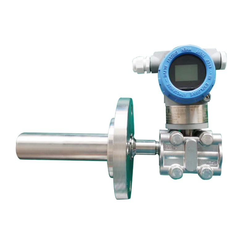
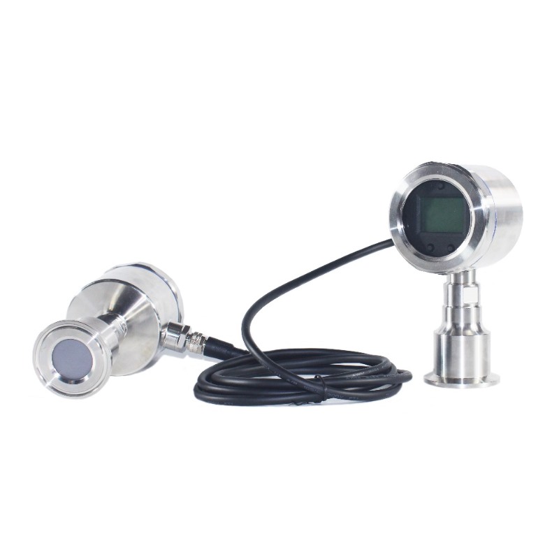
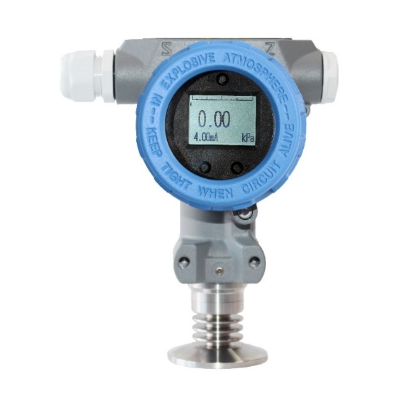
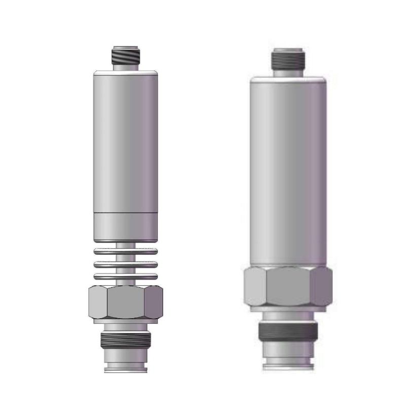
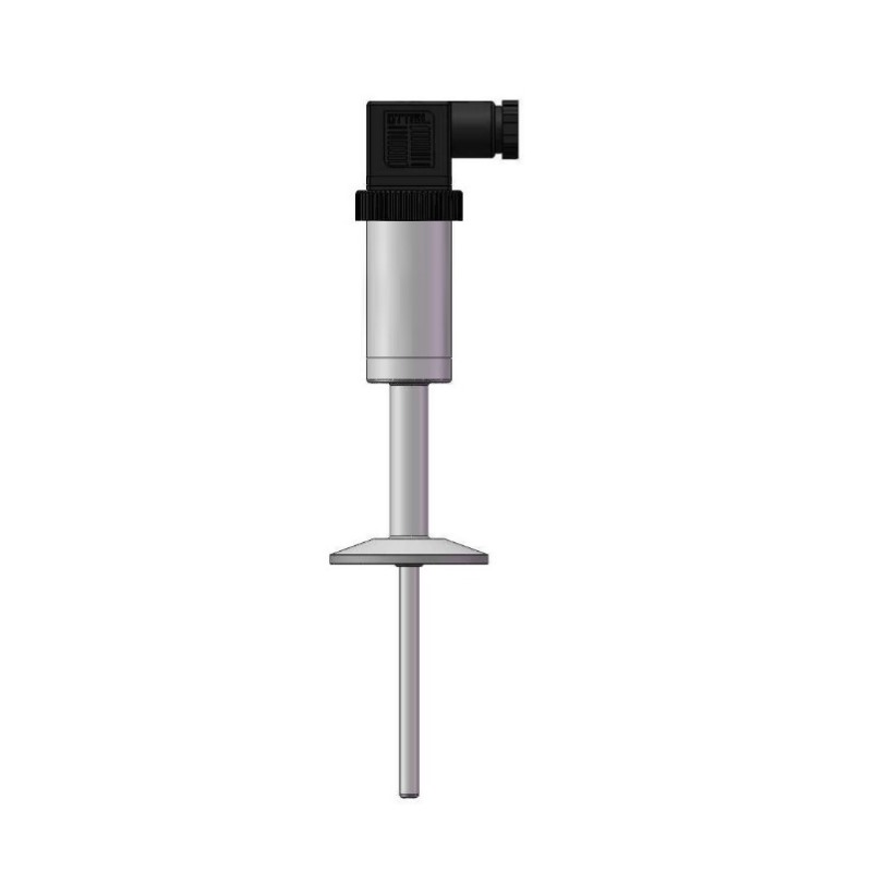
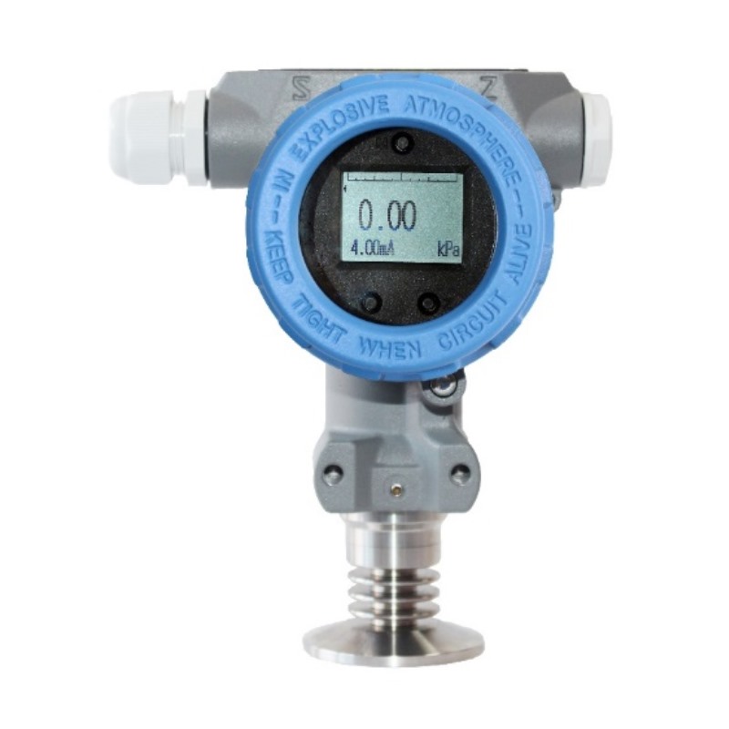
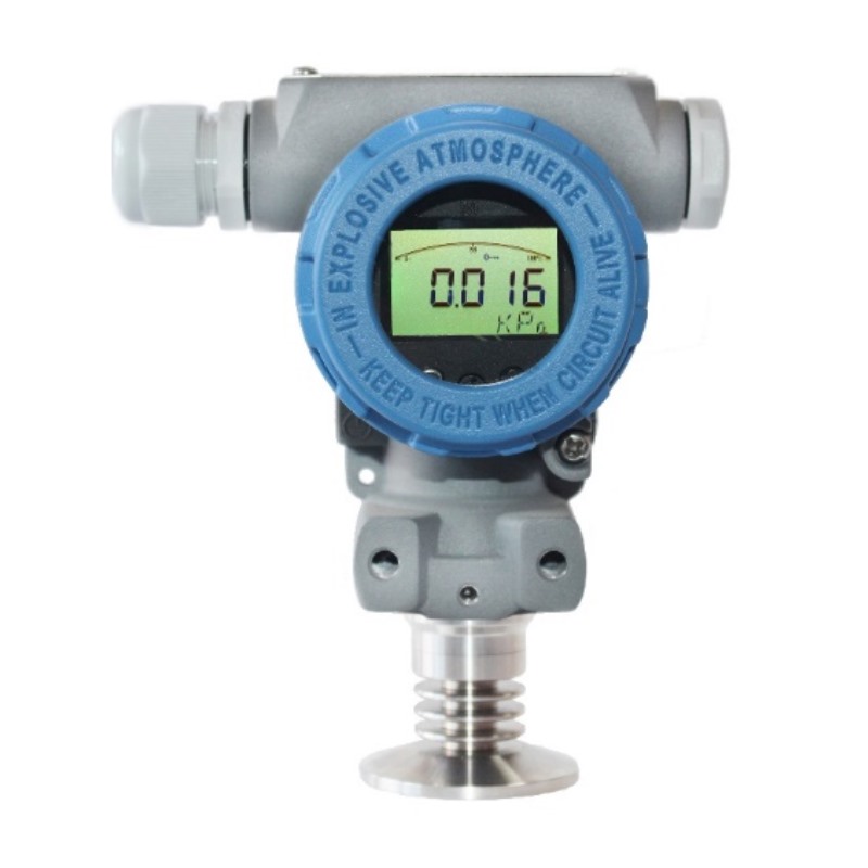
The ADDA-P-1KW sanitary pressure transmitter is designed for pressure and level measurement in food, beverage, pharmaceutical, and bioengineering applications. It uses a sanitary all-stainless-steel structure, 355° rotating LCD module, diffused silicon piezoresistive technology, CIP/SIP cleaning support, 4–20 mA DC + HART or Modbus-RTU/RS485 output, and IP67 protection.

Authoritative Qualification Certifications

We hold ISO quality certification, national high-tech enterprise qualification, China measuring instrument type approval, and explosion-proof and safety certifications to support reliable product quality.

Custom Engineering

Configurable materials, connections, signals, displays, and installation solutions for different process environments.

Product Features

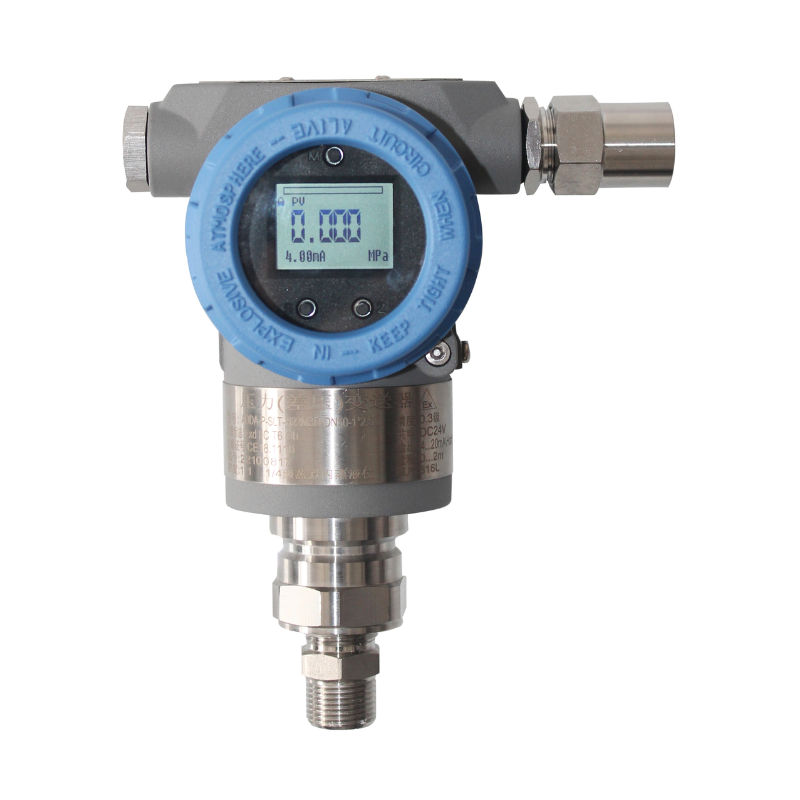
The ADDA-P-1KW smart flush diaphragm pressure transmitter is designed for sanitary applications in food, beverage, pharmaceutical, and bioengineering industries. It features an all-stainless-steel structure and a dot-matrix LCD module that supports 355° rotation. The hygienic design has no dead spaces and is designed to comply with FDA requirements.

  • Uses diffused silicon piezoresistive technology for stable performance, with accuracy up to 0.1%F.S.
  • Hygienic design complies with EHEDG, 3A, FDA, and GMP requirements.
  • Wetted material surface roughness down to Ra 0.4
  • Supports CIP-SIP cleaning, with temperature resistance up to 150 degrees C
  • Uses a high-performance EMC protection circuit module to reduce electromagnetic interference with the output.
  • High stability: ±0.1% Span/year

Applications

Pressure and level measurement in food, beverage, pharmaceutical, and other sanitary applications.

Measuring Medium

Media compatible with the wetted materials.

Performance Specifications

Accuracy±0.1%, ±0.2% , ±0.5% Upper Range Limit, see specifications for details
Range10kPa~40MPa, see selection table for details
Annual Stability±0.1% Span/year
Ambient Temperature Influencesee specifications for details
Voltage InfluenceWhen the supply voltage varies within 10.5V/16.5V~36V DC, the changes in zero point and span shall not exceed ±0.001%URL/V
Mounting Position InfluenceTransmitter installation may cause zero error, this error can be corrected by zero adjustment, with no effect on accuracy
Vibration InfluenceTested according to GB/T18271.3/IEC61298-3 test, < 0.1%
Output Signal4mA~20mADC+HART

Modbus-RTU/RS485

Protection GradeIP67

Range

Pressure TypeNominal RangeMinimum RangeLower Range Limit (LRL)Upper Range Limit (URL)Overload*
G/N20kPa10kPa-20kPa20kPaNominal range × 1.5
35kPa10kPa-35kPa35kPaNominal range × 1.5
80kPa20kPa-80kPa80kPaNominal range × 1.5
150kPa50kPa-100kPa150kPaNominal range × 1.5
300kPa60kPa-100kPa300kPaNominal range × 1.5
700kPa140kPa-100kPa700kPaNominal range × 1.5
1.3MPa260kPa-0.1MPa1.3MPaNominal range × 1.5
2.5MPa500kPa-0.1MPa2.5MPaNominal range × 1.5
4MPa0.8MPa-0.1MPa4MPaNominal range × 1.5
10MPa2MPa-0.1MPa10MPaNominal range × 1.5
25MPa5MPa-0.1MPa25MPaNominal range × 1.5
40MPa8MPa-0.1MPa40MPaNominal range × 1.5
A35kPa10kPa0kPa35kPa105kPa
80kPa20kPa0kPa80kPaNominal range × 1.5
150kPa50kPa0kPa150kPaNominal range × 1.5
300kPa60kPa0kPa300kPaNominal range × 1.5
700kPa140kPa0kPa700kPaNominal range × 1.5
1.3MPa260kPa0kPa1.3MPaNominal range × 1.5
2.5MPa500kPa0kPa2.5MPaNominal range × 1.5
4MPa0.8MPa0kPa4MPaNominal range × 1.5
10MPa2MPa0kPa10MPaNominal range × 1.5
High and low limit setting requirements: lower range value (LRV) and upper range value (URV) must be set within the lower and upper range limits, |URV-LRV|≥ Minimum Range

*The overload values refer to the maximum overload range of the sensor. The maximum overload range of the transmitter ultimately depends on the pressure rating of the process connection.

 Accuracy

Based on standards and reference test conditions, including best fit straight line (BFSL), hysteresis, repeatability. Calibration temperature :20 degrees C ±5 degrees C.
Linear Output AccuracyG/NTD<=5±0.2% Span<=35kPa
±0.1% Span≥80kPa
ATD<=5±0.2% Span<=35kPa
±0.1% Span≥80kPa
Note: TD (Turn down) means turndown ratio , TD= maximum range / current range

Ambient Temperature Influence

Pressure TypeInfluencing QuantityRange
G/N/A± (0.1+0.05TD) % 20 degrees C of  Span<=35kPa
± (0.1+0.02TD) % 20 degrees C of  Span≥80kPa

Environmental Conditions

ItemCondition
Operating Ambient Temperature Range-40 degrees C ~ 85 degrees C, LCD display: -20 degrees C ~ 70 degrees C
Storage Ambient Temperature Range-40 degrees C ~ 100 degrees C, LCD display: -40 degrees C ~ 85 degrees C
Measured Medium Temperature RangeSanitary fill oil: -20 degrees C ~150 degrees C
Operating Ambient Humidity Range5%RH~100%RH@40 degrees C
Hazardous AreaPCECCertificate No.: CE20.2148X Certificate No.: CE23.0612X

Ex ia IIC T6 Ga Ex db IIC T6 Gb

Ex tb IIIC T80 degrees C Db

Time Specifications

Total damping time constant: equals the sum of the electronic circuit component damping time constant and sensor capsule damping time constant
Electronic circuit component damping time: 0s~99s adjustable range
Overall response time: <= 90ms (base instrument response time only, excluding diaphragm system response time)

Electromagnetic Compatibility Environment (current signal only)

No.Test ItemBasic StandardTest ConditionPerformance Level
1Radiated Disturbance (Enclosure)GB/T 9254.1/CISPR2230MHz-1000MHzB (Note 2)
2Conducted Disturbance (DC Power Port)GB/T 9254.1/CISPR220.15MHz-30MHzB (Note 2)
3Electrostatic Discharge (ESD) ImmunityGB/T 17626.2/IEC61000-4-24kV (contact), 8kV (air)A (Note 1)
4RF Electromagnetic Field ImmunityGB/T 17626.3/IEC61000-4-310V/m (80MHz-1GHz)A (Note 1)
5Power Frequency Magnetic Field ImmunityGB/T 17626.8/IEC61000-4-830A/mA (Note 1)
6Electrical Fast Transient/Burst ImmunityGB/T 17626.4/IEC61000-4-42kV (5/50ns, 100kHz)A (Note 1)
7Surge ImmunityGB/T 17626.5/IEC61000-4-54kV (line-to-line)

2kV (line-to-ground)

A (Note 1)
8Conducted Disturbance Immunity Induced by RF FieldsGB/T 17626.6/IEC61000-4-63V (150kHz-80MHz)A (Note 1)
Note 1: For performance level A, performance remains normal within the technical specification limits

Note 2: For performance level B, function or performance may temporarily decrease or be lost, but can recover automatically, actual operating status, storage and data remain unchanged

Power Supply and Load Conditions

ItemOperating Condition 
Power Supply VoltageHART communication protocol: 16.5V~36V DC
Intrinsically safe version: HART communication protocol: 18.5V~28V DC
Modbus-RTU/RS485: 12V~36V DC
Load Resistance0Ω~2119Ω during operation

250Ω~600Ω for HART communication

Transmission Distance< 1000m
Power Consumption
4mA~20mA<= 500mW@24V DC, 20.8mA
Modbus-RTU/RS485<= 240mW@24V DC, 10mA

Related Products

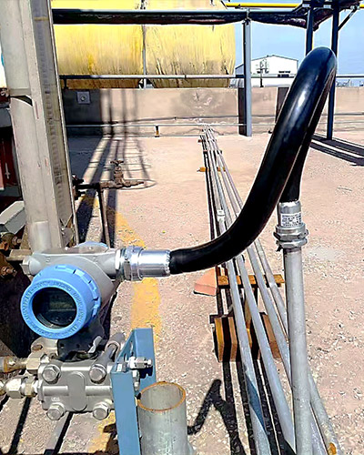
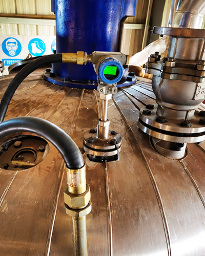
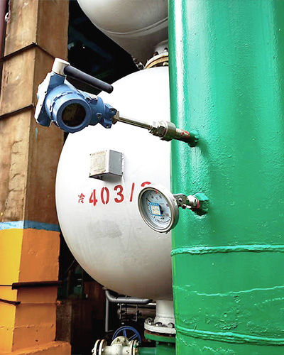
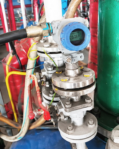
Case Showcase

Frequently Asked Questions

Find quick answers about product selection, customization, technical parameters, delivery, and support for ADDA industrial measurement instruments.

官网询盘

Please provide the measured medium, measuring range, process temperature, process pressure, connection type, output signal, power supply, installation environment, and communication method if remote monitoring is required.

Yes. ADDA can provide customized solutions based on measuring range, process connection, wetted material, display type, communication protocol, installation method, and working environment.

Many ADDA instruments are available with explosion-proof or intrinsically safe configurations. Please confirm the site classification and certification requirements before selection.

Yes. Our team can help recommend a suitable instrument configuration after reviewing your application conditions, including medium, range, connection, output signal, and installation requirements.

Lead time depends on product type, quantity, customization requirements, and certification needs. Standard products usually have a shorter delivery time, while customized models may require additional production time.

Contact Us for Cooperation

官网询盘