
Table of Contents
Intrinsically safe pressure transmitter decisions become clearer when the measurement is tied to a defined operating task. This guide focuses on reviewing the Loop as a System in a process pipeline feeding a packaged industrial skid. The aim is to verify the exact approved assembly and its installation conditions and turn that review into a configuration that can be installed, checked and maintained.
For engineers and purchasing teams, the useful starting point is the process value that must be trusted, the conditions that can make it wrong and the evidence needed before acceptance. The following review connects the sensing method with the physical installation and receiving system. Numerical examples are illustrative calculations, while final model limits and options should be confirmed for the ordered assembly.
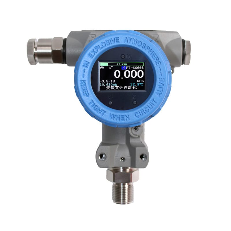
Intrinsically safe pressure transmitter: measurement basis
The intrinsically safe pressure transmitter review should establish one consistent physical basis. Identify power supply, signal type and active or passive connection roles. A two-wire loop, separately powered output and digital bus require different wiring arrangements. Use the exact terminal diagram for the selected configuration.
Range and operating envelope
The operating span must cover the lowest useful reading and the highest normal condition. Startup spikes, cleaning pressure and accidental isolation can impose different demands. Measuring range, allowable overload and pressure boundary rating are separate quantities; a larger electrical span cannot compensate for an inadequate mechanical rating.
For intrinsically safe pressure transmitter, the selected endpoints need a documented operating basis. Compare the exact marking and permitted conditions for the ordered assembly. Gas or dust group, temperature classification, ambient range and any special conditions need review where applicable. Do not combine approvals from different product versions.
Medium and material review
The diaphragm, process fitting, gasket and any isolation valve form a wetted assembly. Stainless steel housing does not identify the diaphragm alloy or seal material. Review the medium composition, concentration and temperature together, particularly where cleaning chemicals differ from the normal process fluid.
A intrinsically safe pressure transmitter specification needs the actual exposure conditions. Keep material, connection and option details alongside the tag. Where certificates or declarations are required, retain the applicable document identity and scope rather than a generic claim.
Intrinsically safe pressure transmitter: installation details
Choose a tap that communicates representative process pressure without excessive vibration or local velocity effects. Plan instrument removal and safe isolation before fitting the connection. Gas pockets in liquid service and condensate in gas service can change the apparent pressure or slow the response.
The installed intrinsically safe pressure transmitter should follow the accepted application drawing. Store the final drawing or measured arrangement. Installation offsets, probe lengths, routes and process tap positions should remain recoverable after personnel or suppliers change.

Signal and configuration
For intrinsically safe pressure transmitter, the receiving value must retain the intended interpretation. For an intrinsically safe arrangement, review the complete circuit and associated equipment rather than only the field transmitter. Interface and power choices can affect the protection basis.
Intrinsically safe pressure transmitter: verification plan
A intrinsically safe pressure transmitter acceptance check needs a reproducible comparison. Agree the acceptance evidence before ordering. Identify dimensional checks, configuration records and functional comparisons that demonstrate the requirements relevant to the project.
Maintenance and fault checks
The intrinsically safe pressure transmitter service record should explain the observed condition. During maintenance, preserve the approved configuration and follow the equipment's service conditions. Unreviewed component, battery, gland or interface changes can alter the assembly's suitability.
Intrinsically safe pressure transmitter: specification for ADDA
A intrinsically safe pressure transmitter inquiry is strongest when its assumptions are explicit. Retain the wiring diagram and observed signal values with the configuration record. This gives maintenance a repeatable starting point when the instrument is replaced or the receiving channel changes.
Review the Smart Gauge / Absolute Pressure Transmitter configuration information and the ADDA product portfolio alongside the tag sheet. These links identify the relevant product family; they do not replace confirmation of the exact ordered materials, interfaces and operating limits.
Practical review: Reviewing the Loop as a System
For an illustrative 0–10 bar gauge span, 12 mA represents 5 bar when the output is linear. A transmitter on a 0–16 bar span gives 8 bar at the same current. These are calculation examples, not model ratings.
To apply this example to intrinsically safe pressure transmitter, begin with the actual drawing and collect the inputs that reviewing the Loop as a System requires. Mark each input as measured, specified or still awaiting confirmation. Compare the result with the normal operating point, then repeat the review at the relevant low or high condition. This makes an assumption visible before it becomes an unexplained offset in the control system.
A practical review should leave three usable records: the physical arrangement that was checked, the configuration that implements the intended interpretation, and the observations used to judge the result. If any one of these changes, identify which conclusions need to be repeated. This is especially useful when a replacement instrument has the same family name but a different range, connection, probe, output or electronics option.
Technology and configuration comparison
| Option | Application consideration | Evidence to request |
|---|---|---|
| Gauge measurement | atmospheric reference and ordinary line pressure | Site requirement supplied by responsible owner |
| Absolute measurement | vacuum reference and pressure calculations | Exact marking and conditions reviewed |
| Differential measurement | two process points and pressure-drop duties | Complete installed assembly inspected |
Use this comparison to structure a intrinsically safe pressure transmitter review, rather than to rank every technology for every process. The preferred option is the one that meets the required measurement task within the available installation and maintenance conditions. Compare supplier offers against the same operating envelope and ask for explicit exceptions when an option cannot meet one of the requirements.
For independent background, consult NIST pressure and vacuum calibration information. This reference provides general technical or metrology context. It is not evidence that a particular ADDA product has been certified, approved or calibrated by that organization.
Discuss your intrinsically safe pressure transmitter application with ADDA. Send the operating data and drawing through the form below, including the specific issue of reviewing the Loop as a System. Request a configuration review, the relevant product information and confirmation of any outstanding application assumptions before placing the order.
Frequently asked questions
Intrinsically safe pressure transmitter: does an intrinsically safe field device establish a safe loop?
The field device is one part of the circuit. Associated equipment, cable parameters and the selected connection arrangement must be reviewed together against the applicable documentation by the responsible project engineer. A product label alone is insufficient.
Intrinsically safe pressure transmitter: can any barrier be used with the transmitter?
The barrier or isolator must be compatible with the approved circuit parameters and installation design. Compare the exact equipment documentation, supply and signal requirements. Do not assume that two devices using a 4–20 mA interface automatically form a suitable protected system.
Intrinsically safe pressure transmitter: why is cable information relevant?
Cable electrical parameters can form part of the circuit assessment. Cable length and type also influence signal and supply performance. Preserve both the protection design information and the ordinary measurement-loop calculation in the project record.
Intrinsically safe pressure transmitter: what changes require renewed review?
A replacement barrier, output option, cable arrangement or power source can affect the circuit basis. Check the proposed change against the exact approved documentation before treating it as an equivalent replacement. Follow the site's engineering change procedure.
Intrinsically safe pressure transmitter: which evidence should accompany the purchase?
Request the precise model marking, applicable documentation, special conditions and terminal information for the offered configuration. Tie these records to the tag and have the responsible engineer confirm their applicability to the site's classified location.