
Produits

Débitmètre à surface variable pour tube métallique ADDA-FL-JS

UGS ADDA-FL-JS Catégorie

Débitmètre à surface variable pour tube métallique ADDA-FL-JS

Débitmètre à surface variable pour tubes métalliques pour liquides, gaz et vapeur Choisissez une indication locale ou un indicateur électronique avec des options de courant, d'impulsion, d'alarme ou de communication sélectionnées De multiples matériaux et dispositions d'installation sont disponibles.

Certifications de qualification faisant autorité

Nous détenons la certification de qualité ISO, la qualification nationale d'entreprise de haute technologie, l'approbation de type d'instrument de mesure de Chine, et les certifications antidéflagrantes et de sécurité pour soutenir la qualité fiable des produits.

Ingénierie personnalisée

Matériaux configurables, connexions, signaux, écrans et solutions d'installation pour différents environnements de processus.
Aperçu | Spécifications | Dimensions | Installation

Metal Tube Variable Area Flow Measurement

The ADDA-FL-JS is a metal tube variable area flow meter for liquids, gases and steam. It is available with local indication or electronic indication and output options. Different measuring-tube, material and installation configurations support low-flow applications and selected high-temperature, high-pressure, corrosive or non-conductive media.

Caractéristiques

  • Self-damping indicator designed to reduce pointer movement.
  • Modular indicator options with local pointer or LCD indication.
  • Electronic versions offer selectable Chinese or English display menus and configurable multi-parameter display screens.
  • Selectable upper and lower flow alarms, pulse output and communication options, depending on the indicator and power arrangement.
  • Measuring-tube and float design with a near-linear scale over multiple tapered sections.

Principe d'exploitation

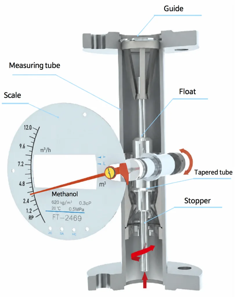
As fluid flows through the measuring tube, it produces an upward force on the float. The float settles where this force balances its effective weight in the fluid. Its position changes the annular flow area and corresponds to flow rate. Magnetic coupling transfers float movement to the indicator. Electronic versions convert the magnetic signal for flow display and totalization.

Variable area flow meter cutaway showing float, guide and magnetic indicator
Variable area measurement structure

Spécifications techniques

ParamètreSpécification
Précision±1.5%
Series flow coverage for water1–200000 L/h at 20°C
Series flow coverage for air0.03–3000 m³/h at 20°C and 0.1013 MPa
Turndown ratio10:1
Nominal sizesDN15–DN200
Viscosity limitsDN15: η < 5 mPa·s; DN25: η < 250 mPa·s; DN50–DN200: η < 300 mPa·s
Power options220 VAC ±5%; 24 VDC ±5%; 3.6 V, 9 Ah lithium battery; or unpowered local indication, depending on configuration
Options de sortiePulse; 4–20 mA; optional HART; Modbus RTU RS485; selected alarm outputs
Enclosure protection optionsIP65, IP66 or IP67, depending on the selected configuration

Flow coverage applies to the series, not to every nominal size. Select the range for the actual fluid, operating conditions and meter configuration.

Pressure and Temperature Options

ConfigurationLimit
Standard pressure, DN15–DN50≤4.0 MPa
Standard pressure, DN80–DN200≤1.6 MPa
Special pressure, DN15–DN50≤32 MPa; consult the factory before selection and ordering
Special pressure, DN80–DN200≤16 MPa; consult the factory before selection and ordering
Jacket pressure rating1.6 MPa
Standard medium temperature−20°C to +120°C
PTFE configuration0°C to +80°C
High-temperature configuration+120°C to +450°C
Low-temperature configuration−80°C to −20°C
LCD operating ambient temperature−30°C to +80°C
Local pointer or local alarm ambient temperature−40°C to +100°C
Flameproof configuration ambient temperature−30°C to +60°C

These limits apply to the configurations shown and must not be combined as a single universal rating. Confirm material, pressure, temperature and indicator compatibility when ordering.

Measuring Tube and Connection Options

CodeArrangementSelection conditions
XSBottom inlet and top outletSelect wetted material and connection for the application
XHBottom inlet and upper side outletPTFE wetted-material option is not available
SHLower side inlet and upper side outletPTFE wetted-material option is not available
YZRight inlet and left outletPTFE wetted-material option is not available
ZYLeft inlet and right outletPTFE wetted-material option is not available
SPHorizontal spring arrangement316 spring; temperature ≤200°C
SXTop inlet and bottom outlet316 spring; temperature ≤200°C
WSSanitary polished tubePTFE wetted-material option is not available
ArticleOptions
ConnectionsFlanged, external threaded or clamp
Wetted materials304 stainless steel, 316L stainless steel, titanium, PTFE or HC
Additional sensor arrangementsJacketed, damped for gas service, high-temperature, low-temperature or high-pressure
Ordering detailsSpecify flange standard and sealing face, thread dimensions or clamp dimensions

Indicator Options

IndicatorConstruction
M1Full-function indicator with a round cast-aluminium enclosure
M2Round machined stainless steel enclosure, with the same external form as M1
M3Round machined stainless steel enclosure, with the same external form as M4
M4Round pressed stainless steel enclosure, Ø125
M5Round pressed stainless steel enclosure, Ø100
M6Square cast-aluminium enclosure

Power and Signal Selection

CodePower and outputCompatibility
AUnpowered local indicationM1 can be selected with a reed-switch alarm output
B220 VAC; 4–20 mA; optional alarm and pulseM5 or M6 indicators only
CBattery-powered local LCDM1 or M6 only; no signal output, backlight or alarm
D24 VDC two-wire; 4–20 mAHART is available with this power option
E24 VDC three- or four-wire; 4–20 mA; optional alarm and pulseAll listed indicators except M5

RS485 is listed only for power options B and E. HART is listed only for power option D. Select LCD or non-LCD indication as applicable.

Alarm and Electrical Options

ArticleSpecification or condition
Electronic flow alarmUpper and lower instantaneous-flow limits; optically isolated Darlington output
Electronic alarm loadInternal 24 VDC supply: maximum 8 mA; external supply: 200 mA at 30 VDC
Local alarmUpper, lower, or upper and lower instantaneous-flow alarm with reed-switch contacts
Reed-switch contact rating1 A at 30 VDC; normally open or normally closed options
Alarm settingsMaximum upper/lower alarm holding range: 60% of span; minimum interval between upper and lower alarm settings: 10% of span
M20 × 1.5 electrical entryM1, M2 or M6 indicators
M16 × 1.5 electrical entryM3, M4 or M5 indicators
Hazardous-area optionThe catalogue lists flameproof Exdb IIC T6 Gb only for the M1 indicator option; non-explosion-protected configurations are also available. Confirm marking and documentation for the ordered product.

Standard M1 Dimensions

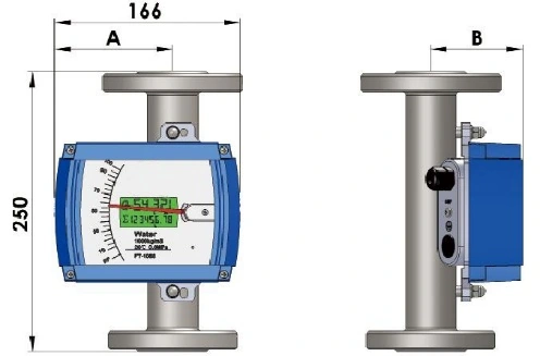
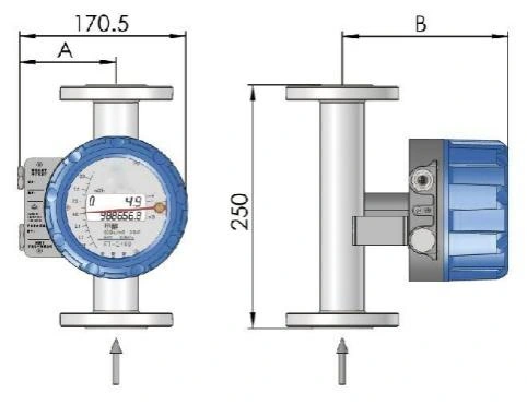
Bottom-inlet, top-outlet arrangement. Dimensions A and B are in millimetres. Approximate weight is in kilograms and pressure loss is in kilopascals.

Metal tube variable area flow meter round indicator and body dimensions
Standard M1 bottom-to-top arrangement
Standard M1 bottom-to-top dimensions — Part 1 of 2
Taille nominaleA mmB standard mmB high-temperature mm
DN15108154194
DN2599173213
DN5084173213
DN8071173213
DN10061213273
DN15042213273
DN20011213273
Standard M1 bottom-to-top dimensions — Part 2 of 2
Taille nominaleApproximate weight kgPressure loss ΔP kPa
DN153.716
DN255.616
DN509.77
DN8015.115
DN1001722
DN15033.760
DN20048.770

Standard M6 Dimensions

Metal tube variable area flow meter rectangular indicator and body dimensions
Standard M6 bottom-to-top arrangement
Standard M6 bottom-to-top dimensions — Part 1 of 2
Taille nominaleA mmB standard mmB high-temperature mm
DN1510674154
DN2510683163
DN5010698178
DN80116111191
DN100116121201
DN150116140220
DN200116170250
Standard M6 bottom-to-top dimensions — Part 2 of 2
Taille nominaleApproximate weight kgPressure loss ΔP kPa
DN153.414
DN255.310
DN509.412
DN8014.816
DN10016.725
DN15033.460
DN20048.470

Installation Guidance

  • Install the meter for the specified flow direction and measuring-tube arrangement.
  • Provide an upstream straight pipe length of 5 × DN and a downstream straight pipe length of 250 mm, as shown in the catalogue installation arrangements.
  • Reserve installation space for a magnetic filter when the medium contains ferromagnetic material. A magnetic filter is not required when such material is absent.
  • Separate straight-pipe accessories can be omitted when the existing upstream and downstream pipework already meets the installation requirements.
  • Confirm the magnetic-filter allowance and the installation dimensions for the selected size and orientation before installation.

Produits connexes

Vitrine

Foire aux questions

Trouvez des réponses rapides sur la sélection des produits, la personnalisation, les paramètres techniques, la livraison et le support des instruments de mesure industriels ADDA.

官网询盘

Veuillez fournir le support mesuré, la plage de mesure, la température du processus, la pression du processus, le type de connexion, le signal de sortie, l'alimentation électrique, l'environnement d'installation et la méthode de communication si une surveillance à distance est requise.

Oui. ADDA peut fournir des solutions personnalisées basées sur la plage de mesure, la connexion au processus, le matériau mouillé, le type d'affichage, le protocole de communication, la méthode d'installation et l'environnement de travail.

De nombreux instruments ADDA sont disponibles avec des configurations antidéflagrantes ou intrinsèquement sûres Veuillez confirmer les exigences de classification et de certification du site avant la sélection.

Oui. Notre équipe peut vous aider à recommander une configuration d'instrument appropriée après avoir examiné vos conditions d'application, notamment le support, la portée, la connexion, le signal de sortie et les exigences d'installation.

Le délai d'exécution dépend du type de produit, de la quantité, des exigences de personnalisation et des besoins de certification Les produits standard ont généralement un délai de livraison plus court, tandis que les modèles personnalisés peuvent nécessiter un délai de production supplémentaire.

Contactez-nous pour la coopération

官网询盘